Rockwell Automation Publication 1734-UM001E-EN-P - July 2013
Appendix
B
Mounting Dimensions
About This Appendix
Read this appendix for mounting dimensions for the following:
• POINT I/O module with a 1734-ADN adapter
• POINT I/O module with a 1734-PDN module
• POINTBlock modules
POINT I/O Module with a
1734-ADN, 1734-ACNR,
1734-AENT, or 1734-APB
Adapter
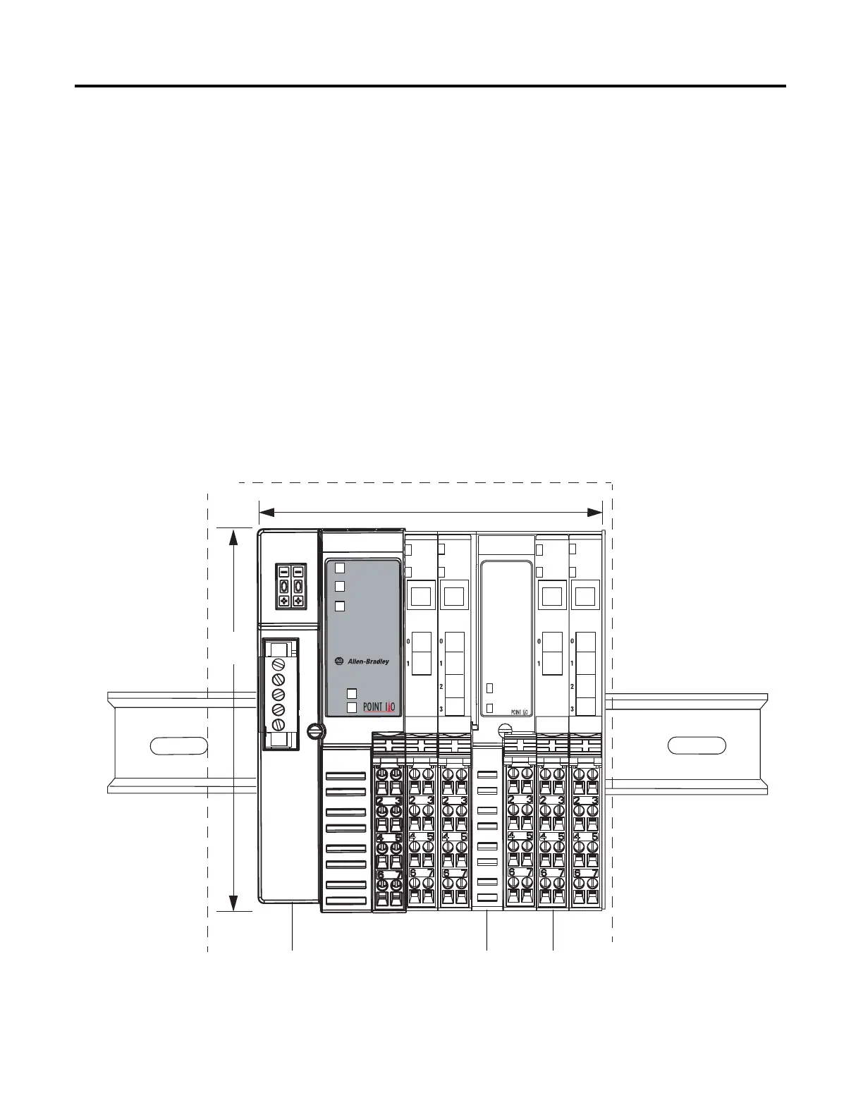
See the figure for mounting dimensions for a POINT I/O module with a
network adapter. The example figure shows a 1734-ADN adapter.
1734-EP24DC or 1734-FPD (HxWxL)
76.2 (3.0) x 25.4 (1.0) x 133.4 (5.25)
1734-EP24DC or 1734-FPD (HxWxL)
76.2 (3.0) x 54.9 (2.16) x 133.4 (5.25)
1734-TB or 1734-TBS with I/O (HxWxL)
76.2 (3.0) x 12.0 (0.47) x 133.4 (5.25)
Secure DIN rail to mounting surface approximately every 200 mm (7.8 in.).
Adapter
Status
DeviceNet
Status
PointBus
Status
1734-ADN
Field
Power
System
Power
L = 2.16 + [# of I/O x 0.47] + [# of EP24DC or FPD x 1.0] in.
Allow a 25.4 (1.0)
air gap all around
133.4
(5.25)
mm (in)
L = 54.9 + [# of I/O x 12.0] + [# of EP24DC or FPD x 25.4] mm
 Loading...


