Publication 1794-6.5.8 - January 2010
104 Input, Output, Status and Configuration Files for Analog Modules when used with ControlNet
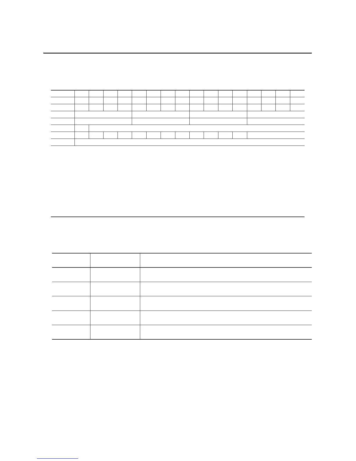
Table 6.2 Output (Configuration) Map
Dec. 15 14 13 12 11 10 9876543210
Oct. 17 16 15 14 13 12 11 10 76543210
Word 0EN000000000000000
Word 1 Channel 3 Filter Channel 2 Filter Channel 1 Filter Channel 0 Filter
Word 2 Ch 3 Configuration Ch 2 Configuration Ch 1 Configuration Ch 0 Configuration
Word 3 0 Real Time Sample Interval
Word 4 IC 1 TR IT 0 CH SK FS RV QK CK GO Channel Number
Word 5 Reserved
Where :
EN = Enable bit (not used on input module)
IC = Initiate Configuration bit
TR = Transparent bit
IT = Interrupt toggle bit
CH - Chop Mode Disable.
SK = FIR Filter Disable
FS = Fast Step Response
RV = Revert to default bit
QK = Quick calibration
CK = Calibration clock
GO = Gain Offset select
Table 6.3
Word/Bit Descriptions for Isolated Analog Input Module
Word Decimal Bit
(Octal Bit)
Definition
Input Word 0 Bits 00-15
(00-17)
Channel 0 analog data – Real time input data per your configuration
Word 1 Bits 00-15
(00-17)
Channel 1 analog data – Real time input data per your configuration
Word 2 Bits 00-15
(00-17)
Channel 2 analog data – Real time input data per your configuration
Word 3 Bits 00-15
(00-17)
Channel 3 analog data – Real time input data per your configuration
Word 4 Bits 00-15
(00-17)
Real Time Sample. The elapsed time in increments programmed by the real time
sample interval.

 Loading...


