Publication 1794-6.5.8 - January 2010
Calibrating Your Module 129
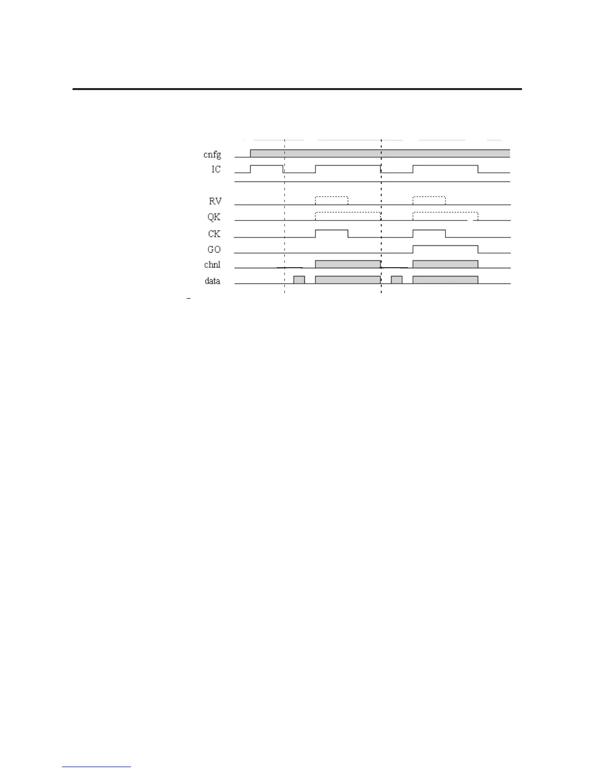
Figure 7.4
Output Calibration Timing Diagram
3. Clear all offset and gain coefficients by:
a. Set output data to 0 and the IC bit to 1
b. With GO = 0, toggle the CK bit
c. With GO = 1, toggle the CK bit
d. Clear the IC bit
4. Send a block transfer write with the output values for offset
voltage to the module (+1560 for 0.5mA mode 8). Measure the
output.
Calculate the offset correction for each channel as follows:
offset_corr = (0.0005 – measured_value) X 1524873.192
5. Enter these offset corrections in the output word for each
channel being calibrated. Record each of the values to be used
later.
6. Send a block transfer write with the IC bit and the CK bit set to
1. With GO low (0), the module copies the “offset_corr”
coefficients (signed 2’s complement format) from the data words
into offset storage for the selected channels. If you set RV high
(1), default values will be copied to all channels.
7. With a BTW, reset the CK bit (0). With the GO bit low (0), the
previously determined offset coefficients are stored in EEPROM
for the selected channel.
8. Monitor the block transfer read. Clear the IC bit to 0. Offset
calibration is completed. Proceed with final gain calibration.
Bit
15
Bit 14
Bit 07
Bit 06
Bit 05
Bit 04
Bit 01 ± 03
Configuration
Gain
Offset
1

 Loading...


