Publication 1794-6.5.8 - January 2010
How to Install Your Analog Module 17
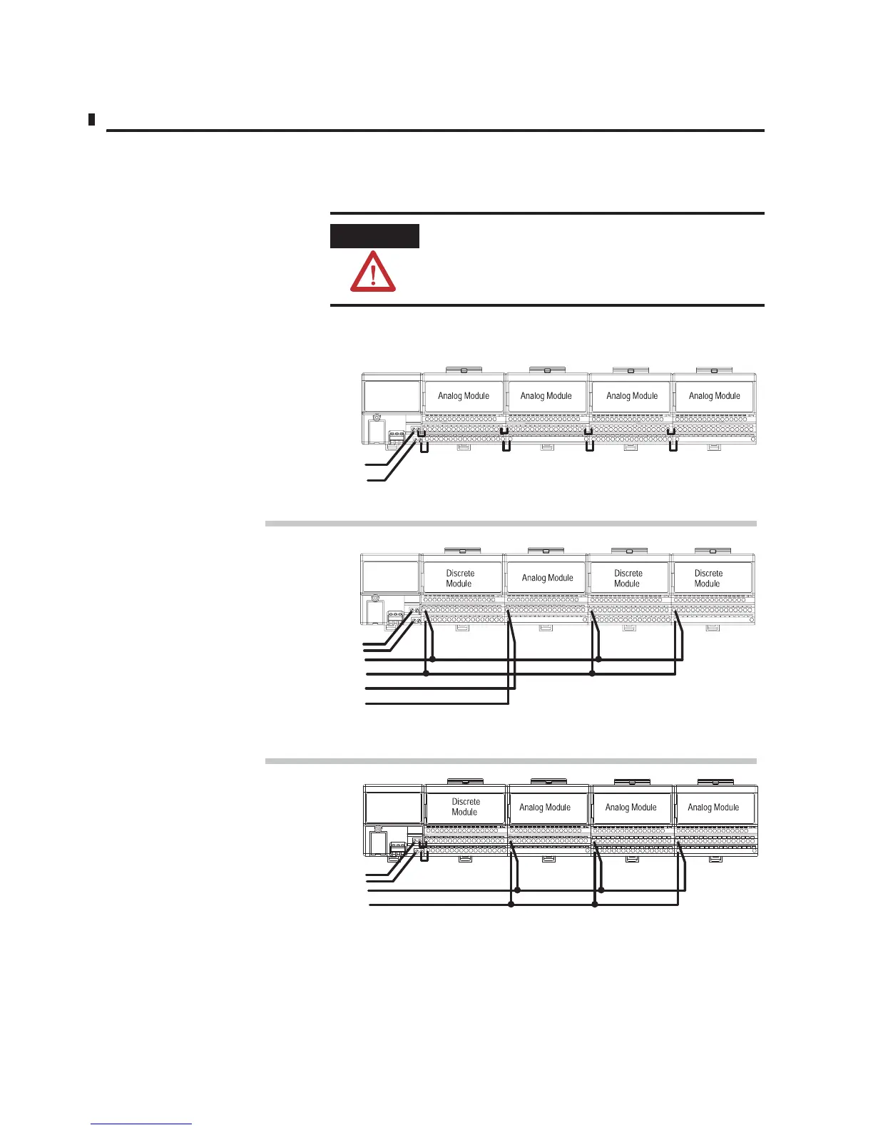
Methods of wiring the terminal base units are shown in the illustration
below.
ATTENTION
Do not daisy chain power or ground from an analog
terminal base unit to any ac or dc discrete module
terminal base unit.
Wiring
when total current draw is less than 10A
W
iring when total current draw is greater than 10A
Daisy-chaining
Individual
T
otal current draw through any base unit must not be greater than 10A
Combination
24V dc
24V dc
24V dc
24V dc
24V dc or
120V ac
24V dc
Note: Use this configuration if using any
ªnoisyº dc discrete I/O modules in your system.
Analog module wiring separate from discrete wiring.
Note: All modules powered by the same power supply
must be analog modules for this configuration.
Note: All modules must be analog modules for this configuration.

 Loading...


