Publication 1794-6.5.8 - January 2010
How to Install Your Analog Module 19
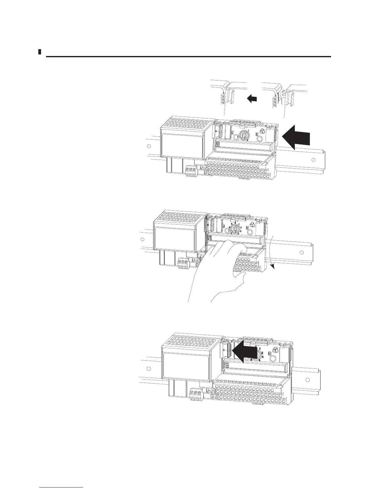
Figure 2.2
4. Repeat steps 1 - 3 to install the next terminal base.
Slide the terminal base unit over tight against the adapter.
Make sure the hook on the terminal base slides under the edge of
the adapter and the flexbus connector is fully retracted.
Press down on the terminal base unit to lock the terminal base
on the DIN rail. If the terminal base does not lock into place,
use a screwdriver or similar device to open the locking tab,
press down on the terminal base until flush with the DIN rail
and release the locking tab to lock the base in place.
Gently push the flexbus connector into the side
of the adapter to complete the backplane connection.
30077-M

 Loading...


