Publication 1794-6.5.8 - January 2010
28 How to Install Your Analog Module
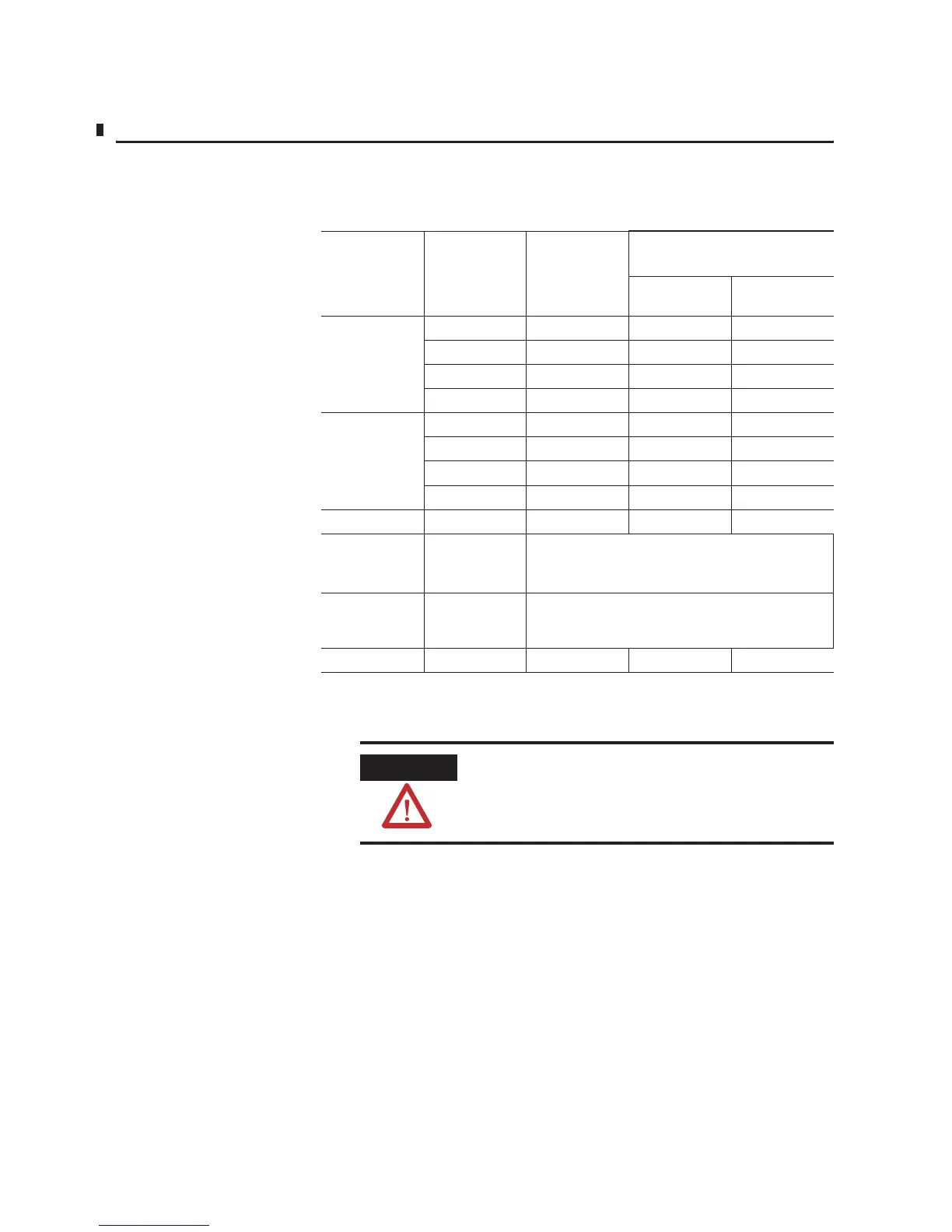
Output 0 Current I2 8
Current I2 Ret 9
Voltage V2 10
Voltage V2 Ret 11
Output 1 Current I3 12
Current I3 Ret 13
Voltage V3 14
Voltage V3 Ret 15
24V dc Common
1794-TB3 – 16 thru 33
(1)
1794-TB3T, -TB3TS – 17, 18, 33
1794-TBN, -TBNF – 16 and 33
+24V dc power 1794-TB3 – 34 thru 51
1794-TB3T, -TB3TS – 34, 35, 50, 51
1794-TBN, -TBNF – 34 and 51
(1)
Terminals 16 thru 33 are internally connected in the terminal base unit.
(2)
Terminal 39 through 46 are chassis ground. Terminals 36, 37, 38 and 47, 48, 49 are used or cold junction compensation.
Table 2.2
Wiring connections for the 1794-IF2XOF2I Isolated Analog Module when using 1794-TB3,
-TB3T, -TB3S, -TB3TS, -TBN and -TBNF Terminal Base Units
Channel Signal Type Label Markings
1794-TB3, -TB3T
(2)
, -TB3S,
-TB3TS
(2)
-TBN, -TBNF
Signal
Terminal
Signal Return
ATTENTION
Total current draw through the terminal base unit is
limited to 10A. Separate power connections to the
terminal base unit may be necessary.

 Loading...


