Publication 1794-6.5.8 - January 2010
62 Writing Configuration to and Reading Status from Your Module with a Remote I/O Adapter
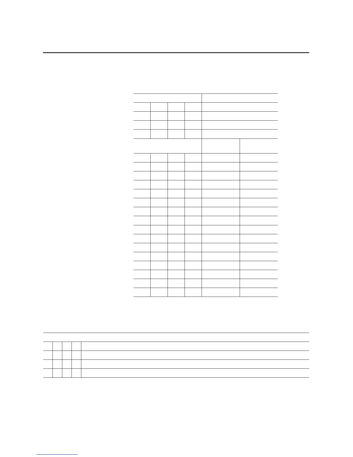
Table 4.7
Setting the Input Filter
Bits Channel
03 02 01 00 Input 0
07 06 05 04 Input 1
11 10 09 08 Input 2
15 14 13 12 Input 3
A/D Conversion
Rate
Low Pass Filter
00001200Hz No low pass
00011200Hz 100ms low pass
00101200Hz 500ms low pass
00111200Hz 1000ms low pass
0100600Hz No low pass
0101600Hz 100ms low pass
0110600Hz 500ms low pass
0111600Hz 1000ms low pass
1000300Hz No low pass
1001300Hz 100ms low pass
1010300Hz 500ms low pass
1011300Hz 1000ms low pass
1100150Hz No low pass
1101150Hz 100ms low pass
1110150Hz 500ms low pass
1111150Hz 1000ms low pass
Table 4.8
Configuring Your Input Module
Input Channel Configuration
03 02 01 00 Set these bits for Channel 0
07 06 05 04 Set these bits for Channel 1
11 10 09 08 Set these bits for Channel 2
15 14 13 12 Set these bits for Channel 3

 Loading...


