156 Rockwell Automation Publication 825-UM004D-EN-P - November 2012
Chapter 11 Testing & Troubleshooting
Contact Output Verification
Disconnect the MCM converter module cable from the connector on the rear
panel of the 825-P. Use the front panel MAIN > TARGETS > ROW 3 function
to check that MCM/CWEFLT, Bit 0, is equal to one. Use MPS Explorer
software to make TRIPC = 0 0 0 0 0 0 0 1 which closes the Trip contact.
Set AUX2C = 0 0 0 0 0 0 0 1. This will cause the AUX2 contact to close. Repeat
the process for AUX3
…AUX6, if present. Ensure that each contact closure
produces the result that is needed in its associated annunciation, control, or trip
circuit [remove control power to close the AUX1 (Alarm) contact].
Self-Tests
The 825-P runs a variety of self-tests. As shown in Table 89, when the relay
detects certain self-test failures, the Critical Alarm Status is latched. A latched
Critical Alarm Status closes the Trip contact and displays the associated message
on the front panel.
When the Critical Alarm Status column in Table 89 shows Not Latched, the trip
contact will not close because of the self-test failure. However, the associated
message (if present) is displayed on the front panel.
All relay self-test failure messages are automatically sent to the serial port.
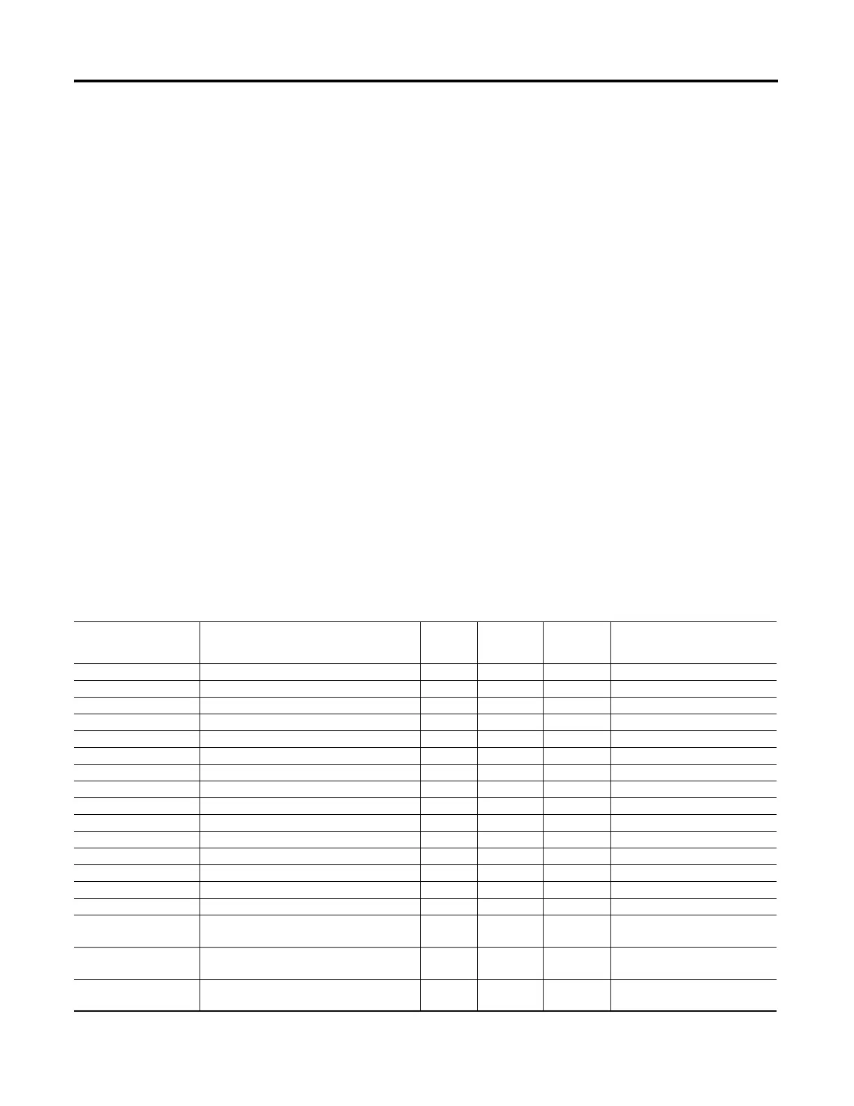
Table 89 - Relay Self-Tests (Sheet 1 of 2)
Self-Test Description Limits
Protection
Disabled on
Failure
Critical
Alarm Status
Front Panel Message
on Failure
External RAM Performs a read/write test on system RAM Yes Latched External RAM FAILED
Internal RAM Performs a read/write test on CPU RAM Yes Latched Coldfire RAM FAILED
CR_RAM Performs a checksum test on the active copy of settings Checksum Yes Latched CR_RAM FAILED
Code Flash Checksum is computed on code base Checksum Yes Latched PROGRAM MEMORY FAILED
Mainboard EEPROM Checksum is computed on critical data Checksum Yes Latched EEPROM FAILED
Data Flash Checksum is computed on critical data Checksum Yes Latched FLASH FAILED
Front Panel Check if ID register matches expected No Not Latched
Voltage Board Check if ID register matches part number Yes Latched VT CALIBRATION FAILED
Current Board Check if ID register matches part number Yes Latched CT CALIBRATION FAILED
I/O Board Check if ID register matches part number Yes Latched I/O BOARD FAILURE
DeviceNet Board DeviceNet card does not respond in 500 ms. Yes Latched DEVICENET BOARD FAILURE
CPU Exception Vector CPU error Yes Latched Vector nn
Loss of MCU Crystal Clock stopped Yes Latched CLOCK STOPPED
Current Board A/D Offset Measure DC offset at each input channel 50 mV No Not Latched
Voltage Board A/D Offset Measure DC offset at each input channel 50 mV No Not Latched
+3.3V Warn Measure +3.3V power supply <3.43V
>3.13V
No Not Latched
+3.3V Fail Measure +3.3V power supply <3.07V
>3.53V
Yes Latched +3.3V FAIL
+5V Warn Measure +5V power supply <5.2V
>4.8V
No Not Latched

 Loading...