116 Rockwell Automation Publication 2198-UM002G-EN-P - February 2019
Chapter 4 Connector Data and Feature Descriptions
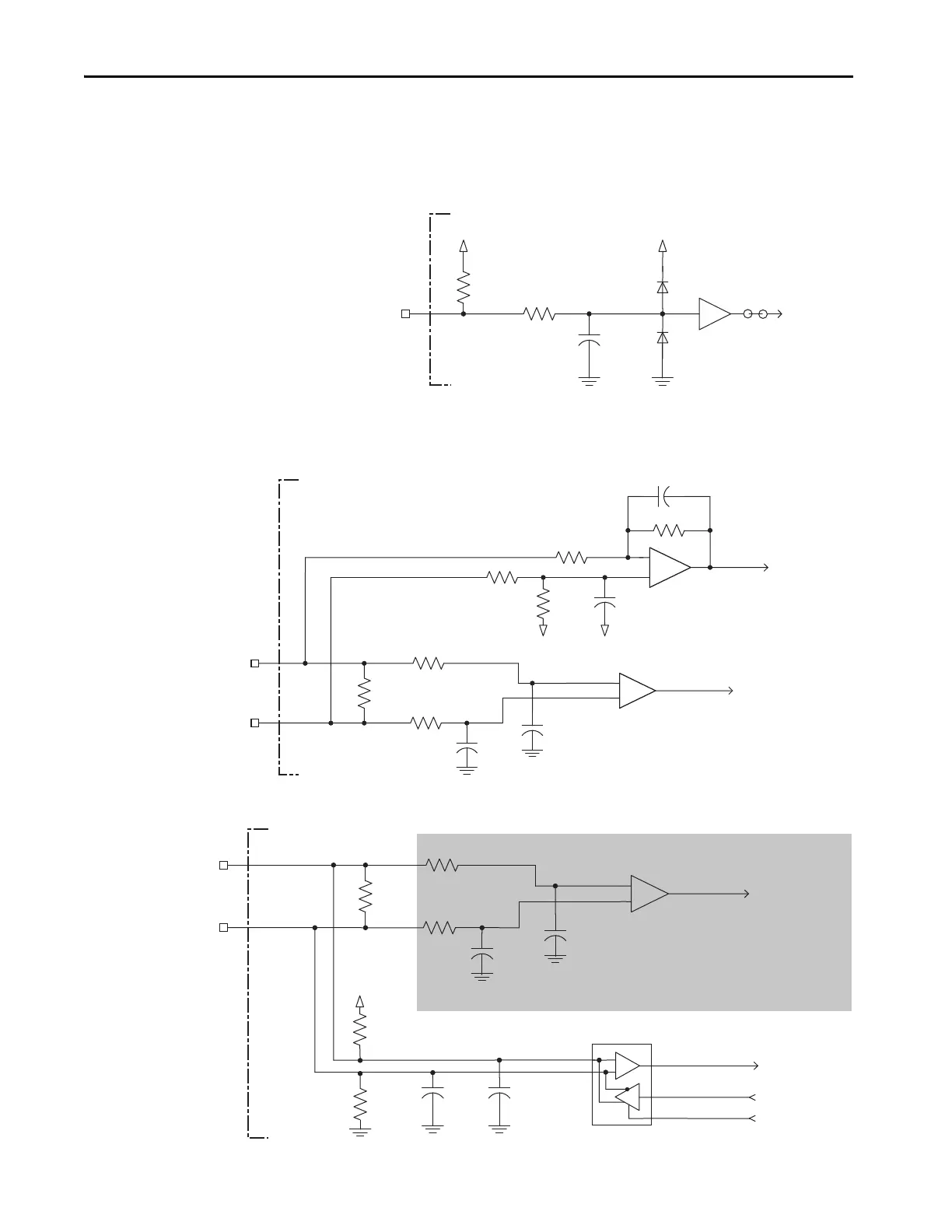
This is the motor thermostat interface schematic. Although the thermostat
signal is shown for all feedback types, some motors may not support this
feature because it is not part of the feedback device.
Figure 69 - Motor Thermostat Interface
Stegmann Hiperface Feedback
Figure 70 - Stegmann Hiperface Interface, MTR_SIN and MTR_COS Signals
Figure 71 - Stegmann Hiperface Interface, MTR_DATA Signals
+5V
1 k
Ω
8.25 k
Ω
0.1
μF
MTR_TS
+5V
Jumper
56 pF
MTR_SIN+ or
MTR_COS+
MTR_SIN- or
MTR_COS-
+
1 k
Ω
+
to AqB Counter
1 k
Ω
1 k
Ω
1 k
Ω
121
Ω
56 pF
220 pF
2 k
Ω
220 pF
to A/D Converter
2 k
Ω
+2.5V
+2.5V
-
-
+
to UART
from UART
from UART
100 pF
MTR_DATA+
MTR_DATA-
1 k
Ω
to AqB Counter
1 k
Ω
1 k
Ω
100 pF
1 k
Ω
121
Ω
56 pF
56 pF
+5V
-
Shaded area indicates components that are part of the circuit, but support
other feedback device types (not used for Stegmann Hiperface support).
Kinetix 5700
Servo Drive
 Loading...


