Rockwell Automation Publication 2198-UM002G-EN-P - February 2019 119
Connector Data and Feature Descriptions Chapter 4
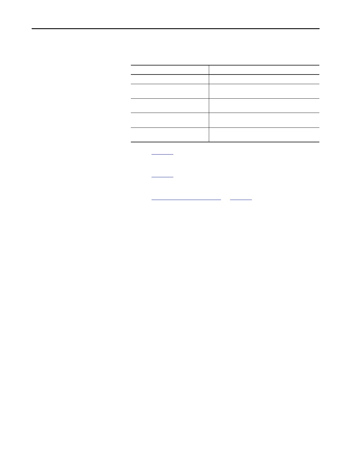
Generic Sine/Cosine Feedback
Table 54 - Generic Sine/Cosine Incremental Specifications
Refer to page 117 for the generic sine/cosine interface schematic. It is identical
to the Stegmann Hiperface (MTR_AM and MTR_BM) signal schematic.
Refer to page 118
for the Hall (MTR_S1, MTR_S2, and MTR_S3) signal
schematic.
Refer to Encoder Phasing Definitions
on page 123 for encoder phasing
alignment diagrams.
Attribute Value
Sine/Cosine interpolation 2048 counts/sine wave period
Input frequency
(MTR_SIN and MTR_COS)
250 kHz, max
Differential input voltage
(MTR_SIN and MTR_COS)
0.6…1.2V, p-p
Commutation verification
Commutation angle verification performed at the first Hall signal
transition and periodically verifies thereafter
Hall inputs
(MTR_S1, MTR_S2, and MTR_S3)
Single-ended, TTL, open collector, or none
 Loading...


