170 Rockwell Automation Publication 2198-UM002G-EN-P - February 2019
Chapter 5 Connect the Kinetix 5700 Drive System
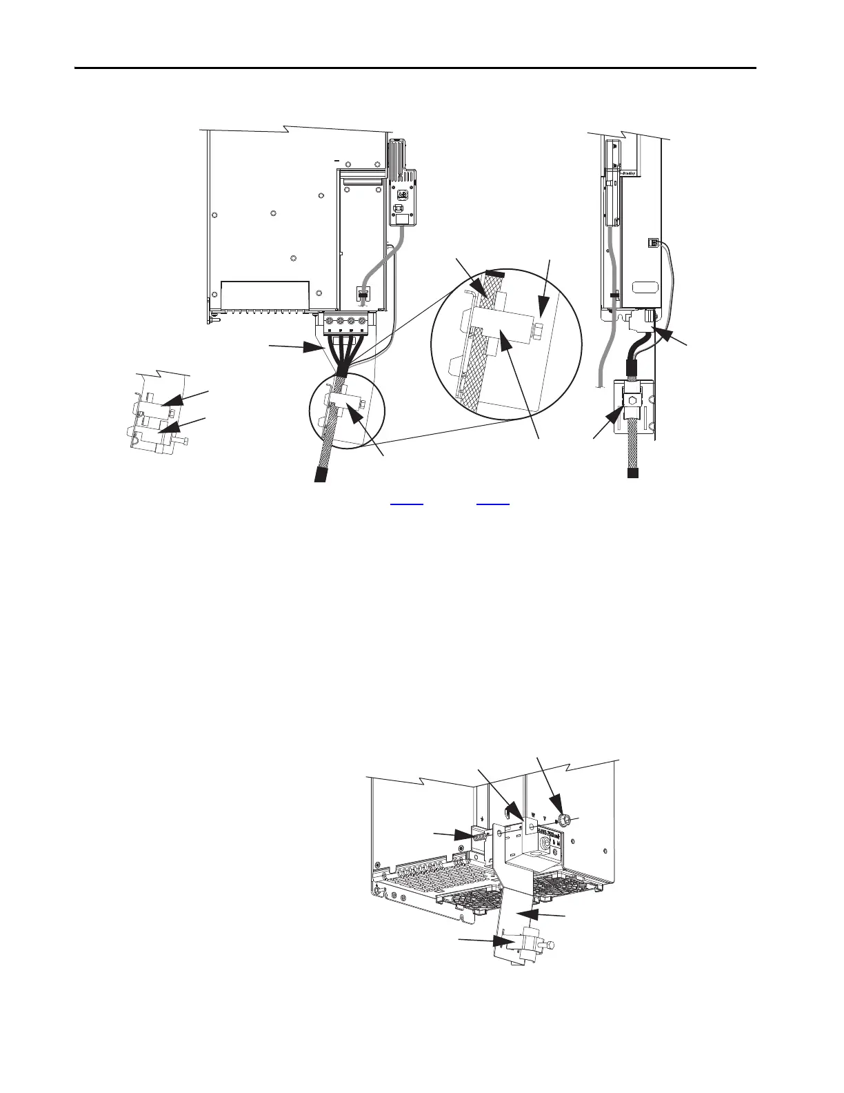
Figure 112 - Single-axis Inverter Cable Installation (series A and B, 10 AWG cables)
5. Repeat step 1 through step 4 for each drive in multi-axis configurations.
Follow these steps to apply the 2198-S263-ERSx and 2198-S312-ERSx single-
axis inverter motor-cable shield clamp when using 2090-CPBM7DF motor
power cables.
1. Install the clamp bracket.
a. Remove the M8 hex nut by using a 13 mm socket.
b. Remove the termination block.
c. Insert the cable clamp bracket over the M8 stud.
d. Replace the termination block and hex nut.
e. Tighten the hex nut to 5.6 N•m (50 lb•in), max.
Motor Cable
Shield Clamp
2198-K57CK-D15M
Motor Feedback
Connector Kit
Motor Power
(MP) Connector
Motor Brake
(BC) Connector
Clamp Screw
(M10)
2198-Sxxx-ERSx
Single-axis Inverter
(front view)
Small Cable Clamp
Overall Cable Shield
Under Clamp
Motor Power Wires
Bulletin 2090-CPBM7DF
Power/Brake Cable
Small Cable Clamp
(10, 8, and 6 AWG)
Large Cable Clamp
(4 and 2 AWG)
M8 Hex Nut
2198-S263-ERSx or
2198-S312-ERSx
Single-axis Inverter
(front/side view)
Cable Clamp
Cable Clamp
Bracket
Ground Conductor
Termination Block
M8 Stud
 Loading...


