Rockwell Automation Publication 2198-UM002G-EN-P - February 2019 171
Connect the Kinetix 5700 Drive System Chapter 5
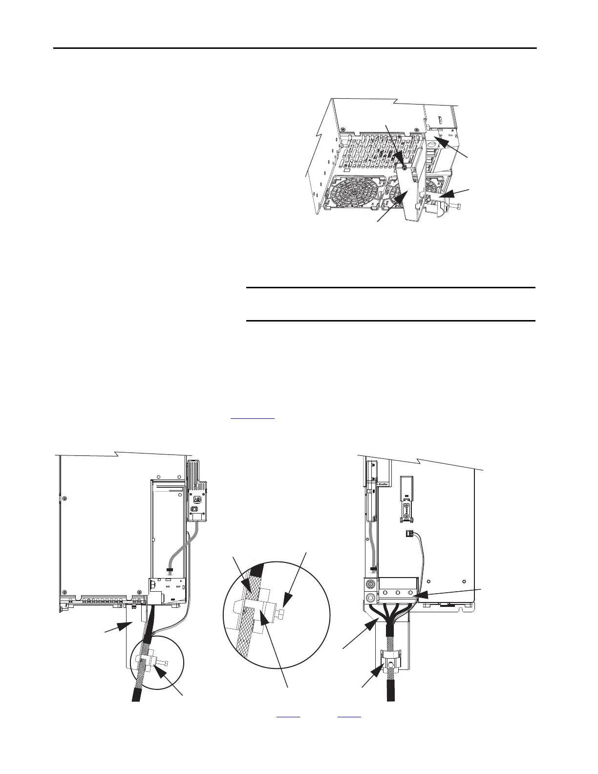
2. Align the clamp-bracket captive screw with hole in chassis and tighten to
1.6 N•m (14 lb•in).
3. Loosen the clamp screw.
4. Position the exposed portion of the cable braid directly in line with the
clamp.
5. Tighten the clamp screw.
Make sure the cable clamp tightens around the overall cable shield and
provides a good bond between the cable shield and the drive chassis.
Torque value 5.6 N•m (50 lb•in), max.
In Figure 113
, the Bulletin 2090 (4 and 2 AWG) cable requires no preparation.
Figure 113 - Single-axis Inverter Cable Installation (4 and 2 AWG cables)
6. Repeat step 1 through step 5 for each drive in multi-axis configurations.
2198-S263-ERSx or
2198-S312-ERSx
Single-axis Inverter
(bottom view)
Cable Clamp
Cable Clamp Bracket
Ground Conductor
Termination Block
Captive Screw
IMPORTANT Make sure the clamp is aligned with the shield braid and not the
heat shrink.
MBRK
+
-
21mm (4 AWG-250 kcmil)
15-20 Nm (132-177 lbin)
2
W V U
Motor Cable Shield Clamp
2198-K57CK-D15M
Motor Feedback
Connector Kit
Motor Power
(MP) Connector
Motor Brake
(BC) Connector
Clamp Screw
(M10)
2198-S263-ERSx or
2198-S312-ERSx
Single-axis Inverter
(front view)
Overall Cable Shield
Under Clamp
Motor Power
Conductors
Bulletin 2090-CPBM7DF
Power/Brake Cable
Cable Clamp
Cable Clamp
Bracket
2198-S263-ERSx or
2198-S312-ERSx
Single-axis Inverter
(side view)
 Loading...


