Rockwell Automation Publication 2198-UM002G-EN-P - February 2019 221
Configure and Start the Kinetix 5700 Drive System Chapter 6
The Feedback Devices are configured for either the DSL Feedback Port
or the Universal Feedback Port.
3. From the Axis x pull-down menu, choose an axis to assign to that motor
feedback or auxiliary feedback device.
4. From the Feedback Device pull-down menu, choose either DSL
Feedback x Port or Universal Feedback x Port to associate with each
axis.
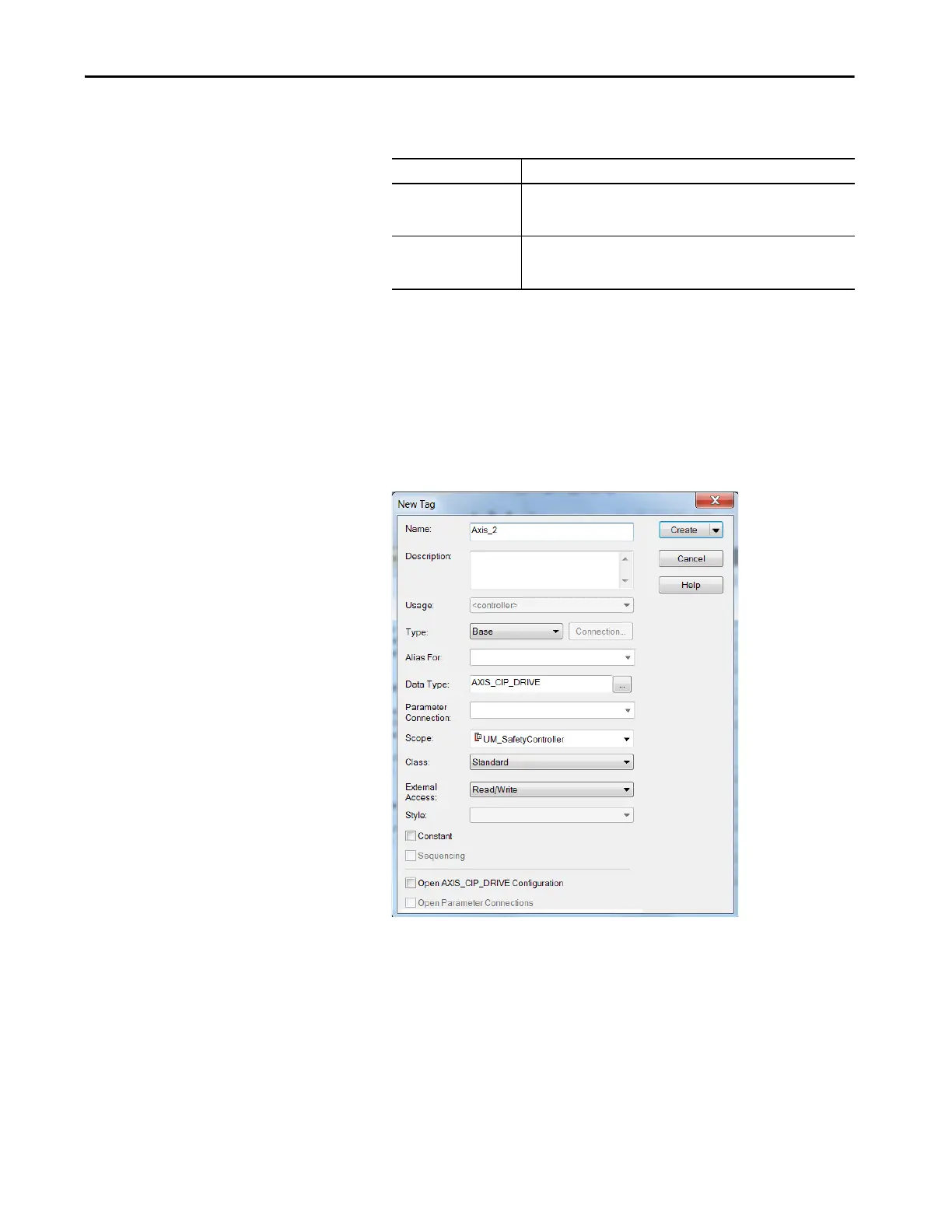
5. Click New Axis.
The New Tag dialog box appears.
6. Type the axis Name.
AXIS_CIP_DRIVE is the default Data Type.
7. Click Create.
Motor Feedback Options Description
DSL Feedback Port
Applies to motors and actuators compatible with the 2198-KITCON-DSL
connector kit and 2198-H2DCK converter kit (series B or later). These kits
plug into the 2-pin motor feedback (MF) connector.
Universal Feedback Port
Applies to motors and actuators compatible with the 2198-K57CK-D15M
universal connector kit. These kits plug into the 15-pin universal feedback
(UFB) connector.
 Loading...


