222 Rockwell Automation Publication 2198-UM002G-EN-P - February 2019
Chapter 6 Configure and Start the Kinetix 5700 Drive System
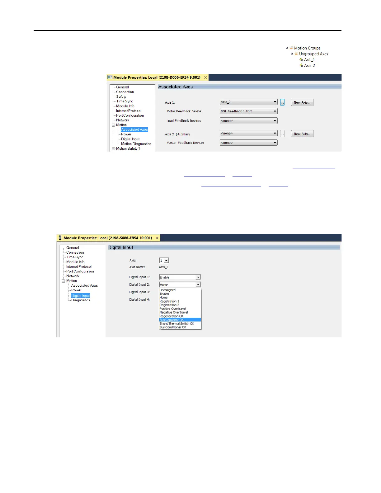
The axis (Axis_1 in this example) appears in the
Controller Organizer under Motion Groups>
Ungrouped Axes and is assigned as Axis 1.
8. Click Apply.
9. Click the Digital Input category.
10. From the Digital Input pull-down menus choose the functions
appropriate for your application.
In this example, Digital Input 2 is assigned Bus Capacitor OK to
monitor your 2198-CAPMOD-2240 capacitor module.
For 8720MC-RPS power supplies:
• When a 2198-Sxxx-ERSx single-axis inverter is the first drive module
(adjacent to the 2198-CAPMOD-2240 capacitor module) you must
configure the Digital Input category as Regeneration OK and wire
the IOD connector.
• When a 2198-Dxxx-ERSx dual-axis inverter is the first drive module
(adjacent to the 2198-CAPMOD-2240 capacitor module) and Axis
1 and 3 are used, you must configure the Digital Input category as
Regeneration OK and wire the IOD connector for each axis.
TIP You can configure an axis as Feedback Only. Refer to Configure Feedback-
only Axis Properties on page 230 for more information.
Refer to Configure Module Properties
on page 256 for configuring motor
feedback, load feedback, and master feedback devices.
 Loading...


