Rockwell Automation Publication 2198-UM002G-EN-P - February 2019 297
Remove and Replace Drive Modules Chapter 8
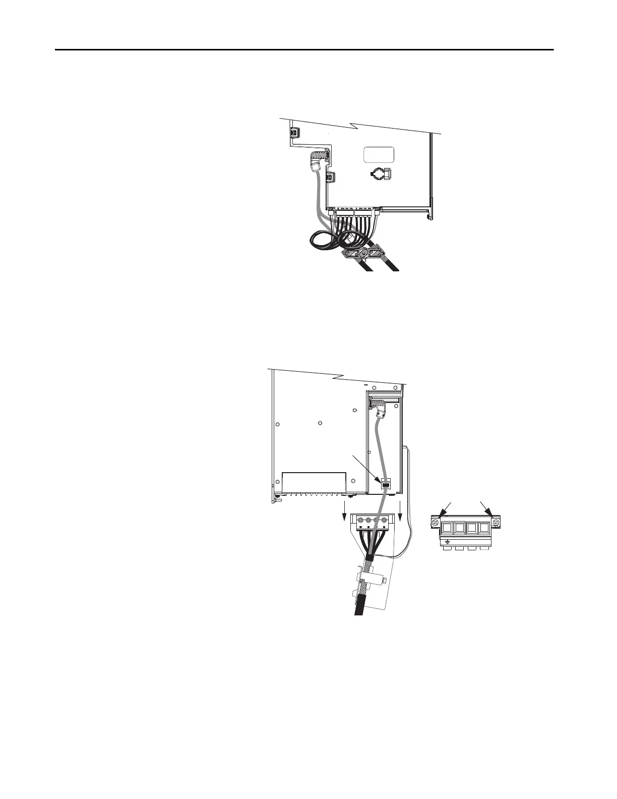
7. For 2198-Dxxx-ERSx dual-axis inverters, unplug the motor feedback,
motor power, and motor brake connectors and loosen the shield clamp
until you can remove the cable from the clamp.
8. Single-axis inverters differ by catalog number in how the motor cable
bracket attaches to the drive, when the bracket is used.
a. For 2198-S086-ERSx, 2198-S130-ERSx, and 2198-S160-ERSx
single-axis inverters, unplug the motor feedback and brake
connectors, remove the tie wrap, and remove the motor power
bracket.
Motor Feedback
Connectors
Motor Power and
Brake Connectors
Loosen Motor Cable
Shield Clamp
2198-Dxxx-ERSx
Dual-axis Inverters
Motor Feedback
Connector
Bracket Screws
Motor Cable Bracket
2198-S086-ERSx,
2198-S130-ERSx,
2198-S160-ERSx,
Single-axis Inverters
Motor Brake
Connectors
Motor Power Connector
(bottom view
Tie Wrap
 Loading...


