298 Rockwell Automation Publication 2198-UM002G-EN-P - February 2019
Chapter 8 Remove and Replace Drive Modules
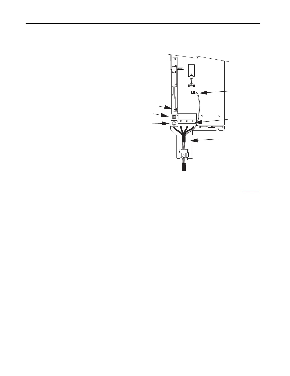
b. For 2198-S263-ERSx and 2198-S312-ERSx single-axis inverters,
unplug the motor feedback and brake connectors, and remove the tie
wrap holding the feedback cable.
If your axis uses 2090-CPBM7DF power/brake (2 or 4 AWG) cable,
remove the motor power cable and bracket from the drive (do not
loosen the shield clamp). Refer to the steps and illustrations on page 170
to see how the bracket is attached.
If your axis uses customer-supplied cable (larger than 2 or 4 AWG), the
motor cable bracket does not apply.
MBRK
+
-
21mm (4 AWG-250 kcmil)
15-20 Nm (132-177 lbin)
2
W V U
Motor Feedback
Connector
Motor Cable Bracket
2198-S263-ERSx,
2198-S312-ERSx,
Single-axis Inverters
Motor Brake
Connectors
Tie Wrap
Motor Power
Connector Screws
M8 Hex Nut
Ground Conductor
Termination
Shield Clamp
 Loading...


