EasyManuals Logo

Allen-Bradley Kinetix 5700 Series User Manual

Allen-Bradley Kinetix 5700 Series
460 pages
To Next Page IconTo Next Page
To Previous Page IconTo Previous Page
Page #299 background imageLoading...
Page #299 background image
Rockwell Automation Publication 2198-UM002G-EN-P - February 2019 299
Remove and Replace Drive Modules Chapter 8
9. For 2198T-W25K-ER iTRAK power supplies, unplug the iPS ready
connector, 24V control power output connectors, and DC-bus output
connectors.
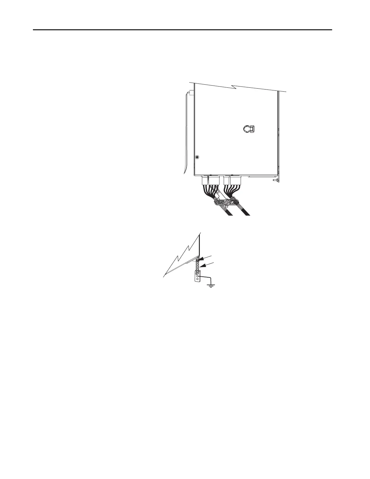
10. Loosen the shield clamp until you can remove the cable from the clamp.
11. Remove the ground screw or lug nut and braided ground strap.
iTRAK PS Ready
Connector
DC-bus and 24V
Output Connectors
Loosen Motor Cable
Shield Clamp
2198T-W25K-ER
iTRAK Power Supply
Ground Screw or Lug Nut
Kinetix 5700 Drive Module
Braided Ground Strap

Table of Contents

Other manuals for Allen-Bradley Kinetix 5700 Series

Questions and Answers:

Question and Answer IconNeed help?

Do you have a question about the Allen-Bradley Kinetix 5700 Series and is the answer not in the manual?

Allen-Bradley Kinetix 5700 Series Specifications

General IconGeneral
BrandAllen-Bradley
ModelKinetix 5700 Series
CategoryServo Drives
LanguageEnglish

Related product manuals