348 Rockwell Automation Publication 2198-UM002G-EN-P - February 2019
Appendix A Interconnect Diagrams
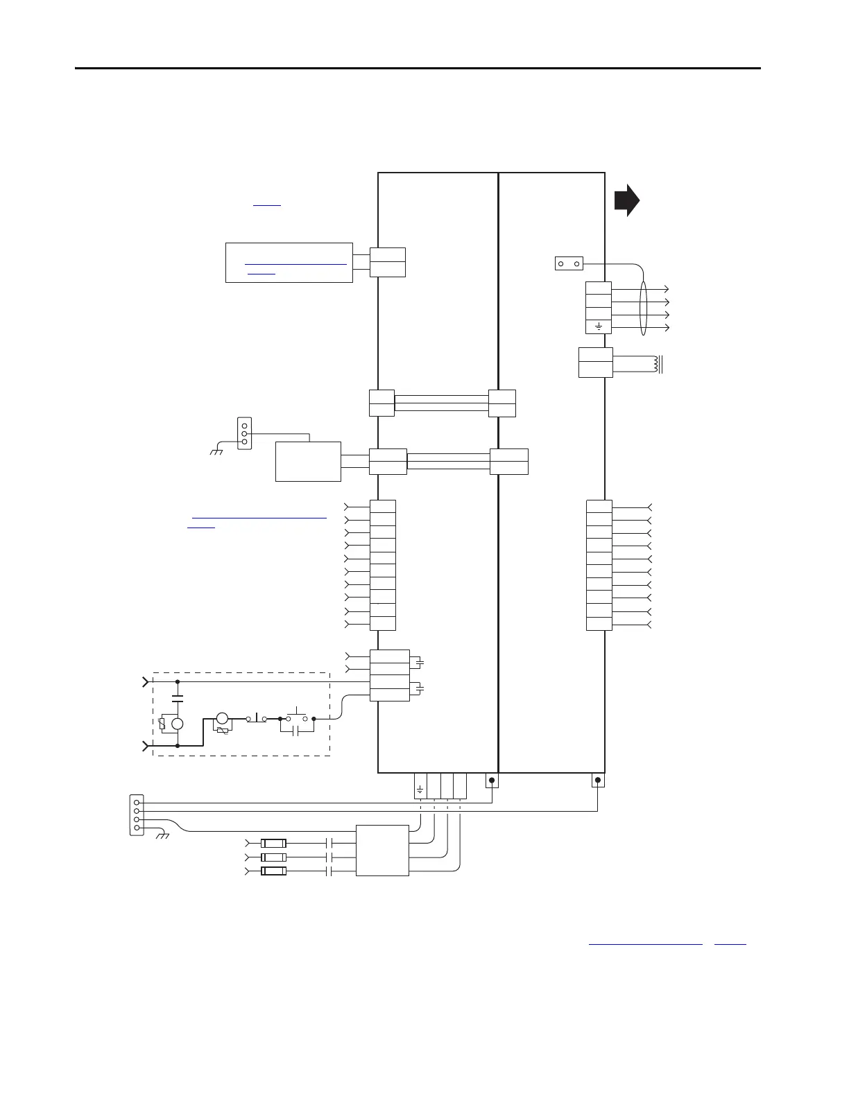
In this example, the inverter drives and optional accessory modules are
downstream of a 2198-RPxxx regenerative bus supply.
Figure 171 - Regenerative Bus Supply Configuration
(1) Use 2198-TCON-24VDCIN36 input wiring connector with 2198-RP088 and 2198-RP200 bus supplies. Use 2198T-W25K-P-IN
input wiring connector with 2198-RP263 and 2198-RP312 bus supplies. See CP Connector Wiring - Shared Bus
on page 146 for
wiring specifications.
24V_COM
+24V
2
1
24V_COM
+24V
DC+
DC-
DC+
DC-
DC+
DC–
1
2
3
4
5
6
7
8
9
10
U
V
W
4
3
2
1
L3 L2 L1
EN+
EN–
IN1
COM
IN2
SHLD
COM
IN3
COM
IN4
COM
SHLD
MBRK -
MBRK +
MBRK -
MBRK +
2
1
1
2
3
4
5
6
7
8
9
10
IN1
COM
IN2
SHLD
COM
IN3
COM
IN4
COM
SHLD
CONV OK+
CONV OK–
CONT EN+
CONT EN–
OK+
OK–
324…506V AC rms
Three-phase Input
Notes 1, 2
Bonded Cabinet
Ground Bus *
Control Power
(CP) Connectors
Three-phase Input
(IPD) Connector
2198-DBRxx-F
Three-phase
AC Line Filter
Note 5
* Indicates User Supplied Component
Chassis
Customer Supplied
+24V DC
Power Supply *
Refer to table on page 341
for note information.
DC Bus
(DC) Connectors
2198-RPxxx
Regenerative Bus Supply
2198-Sxxx -ERSx or
2198-Dxxx -ERSx
Inverter
PE Ground
Note 11
Contactor Enable
(CED) Connector
Note 18
2198-xxxx-P-T
T-connectors and Bus Bars
Refer to Attention statement (Note 17).
STOP *
PE Ground
Note 11
Bonded Cabinet
Ground Bus *
Shunt Power
(RC) Connector
START *
CR1 *
CR1 *
CR1 *
M1 *
Notes 13,18
24V AC/DC
50/60 Hz
Grounding Screws/Jumpers
Note 15
Circuit
Protection*
Note 2
Motor Brake
(BC) Connector
Three-phase
Motor Power
Connections
Notes 8,19
Motor Power
(MP) Connector
Cable Shield
Clamp
Digital Input
(IOD) Connector
Note 9
Motor Brake
Connections
Note 8
Digital Input
Connections
Note 8
Additional Inverters or
Accessory Modules
Note 7
Digital Input
(IOD) Connector
Note 9
M1
Contactor
Note 13
Note 8
2198-TCON-24VDCIN36
(1)
or 2198T-W25K-P-IN
24V Input Power
Wiring Connector
Active Shunt (optional component)
See External Active-shunt Connections
on page 183 for more information.
Digital Input
Connections
See Contactor Wiring for Regenerative Bus Supply on
page 358
for M1 auxiliary contact wiring example.
 Loading...


