354 Rockwell Automation Publication 2198-UM002G-EN-P - February 2019
Appendix A Interconnect Diagrams
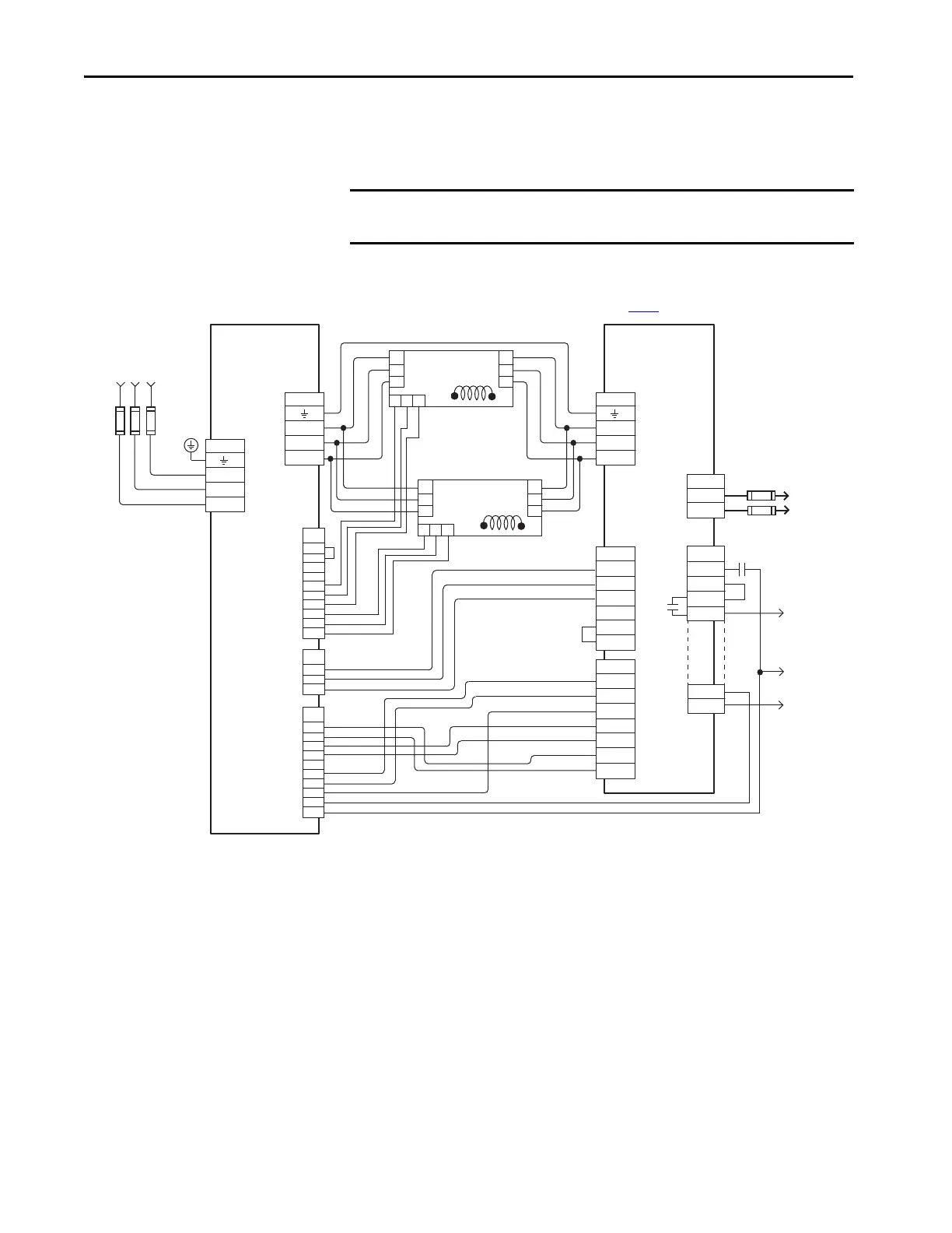
In this example, three-phase AC input power is fed to the 8720MC-RPS190
unit. The DC-bus (TB1) terminals connect to the Kinetix 5700 DC-bus via
the DC-bus conditioner module because the system current exceeds 104 A.
Figure 176 - 8720MC-RPS190 Unit with Kinetix 5700 Drive System
IMPORTANT The 8720MC-RPS regenerative power supply is not compatible with the
iTRAK power supply.
L1
L2
L3
TB1
TB1
DC+
DC-
L1
L2
L3
TB1
L4
L5
L6
TB1
L1 AUX
L2 AUX
L3 AUX
PR1
PR2
PR3
TB2
L1
L2
L3
L4
L5
L6
RED
BLK
YLW
Fan 2
CN1
A1
A2
A3
A4
A5
B1
B2
B3
B4
B5
CN2
A1
A2
A3
A4
A5
B1
B2
B3
B4
B5
CN4
1
2
3
+24V3
0V3
SENS
+24V2
0V2
MC1
TB4
MC2
R1
S1
T1
MC1
MC2
+24V2
0V2
NC
+24V3
0V3
SENS-out
+24V
MC
RED
WHT
BLU
RED
BLK
YLW
L1
L2
L3
L4
L5
L6
Fan 3
TB3
MC
0V
COM
RDY
+24V DC
PWR
P
N
MC *
Note 12
8720MC-RPS190BM
Regenerative
Power Supply
324…506V AC rms
Three-phase Input
Note 3
8720MC-EF190-VB
AC Line Filter
* Indicates User Supplied Component
8720MC-LR10-100B
Line Reactor
Circuit
Protection *
Refer to table on page 341
for note information.
Circuit
Protection *
DC Bus to
Kinetix 5700
Drive System
8720MC-LR10-100B
Line Reactor
Regeneration OK
to Digital Inputs
Aux Contact to
Control String
Note 6
Note 6
Note 6
 Loading...


