356 Rockwell Automation Publication 2198-UM002G-EN-P - February 2019
Appendix A Interconnect Diagrams
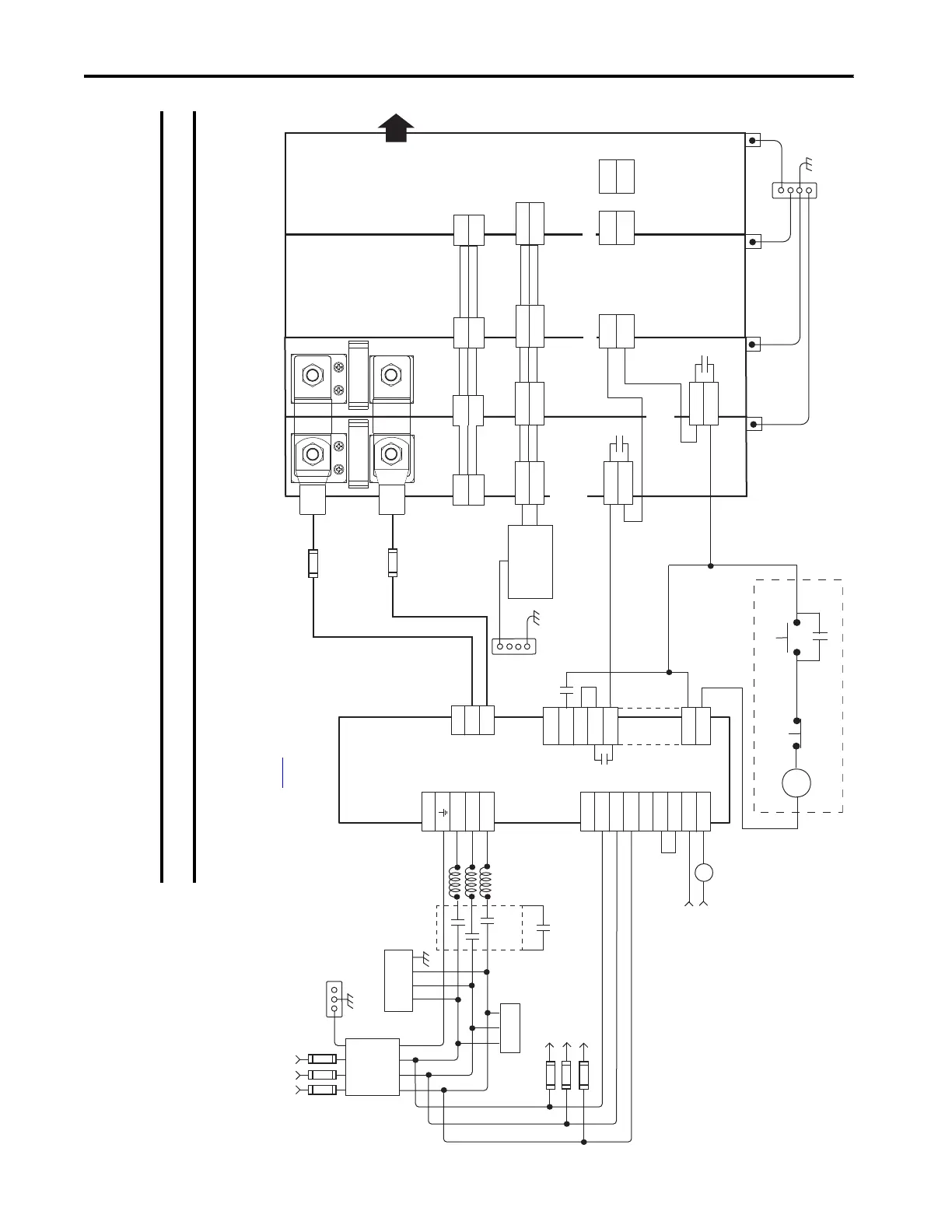
In this example, three-phase AC input power is fed to the Bulletin 8720MC-RPS065 regenerative power supply. The
DC-bus voltage supplies the Kinetix 5700 DC-bus via the 2198-CAPMOD-2240 capacitor module. In configurations
that exceed 104 A, up to a maximum of 208 A, the DC-bus conditioner module is also required.
Figure 177 - 8720MC-RPS with Kinetix 5700 Drive System
IMPORTANT The 8720MC-RPS regenerative power supply is not compatible with the iTRAK power supply.
E/N
L1
L2
L3
G
R
S
T
TB1
CR1*
CR1*
L1 AUX
L2 AUX
L3 AUX
PR1
PR2
PR3
MC1
MC2
TB2
R1
S1
T1
MC
TB1
DC+
DC-
P
N
TB3
MC
0V
COM
RDY
+24V DC
PWR
R S T
24V_COM
+24V
DC+
DC-
2
1
24V_COM
+24V
DC+
DC-
24V_COM
+24V
DC+
DC-
I/O - B
2
1
I/O - A
I/O
24V_COM
+24V
DC+
DC-
2
1
2
1
COM
INx
MS
MS
MS
MS
COM
INx
COM
INx
Refer to Attention statement (Note 17).
MC *
Note 12
Note 16
8720MC-RPS065
8720MC
Regenerative
Power Supply
324…506V AC rms
Three-phase Input
Note 3
Bonded Cabinet
Ground Bus *
Three-phase
AC Line Filter
Note 5
* Indicates User Supplied Component
Harmonic
Filter
Varistor
To Motor Fan
Motor Fan Fusing *
Line
Reactors
Circuit
Protection *
Customer
Supplied
120V AC
Start *
Stop *
Refer to table on page 341
for note information.
2198-CAPMOD-2240
Capacitor Module
PE Ground
Note 11
2198-xxxx-P-T
T-connector
and Bus Bar
PE Ground
Note 11
Bonded Cabinet Ground Bus *
PE Ground
Note 11
Chassis
Note 6
Customer Supplied
+24V DC
Power Supply *
Bonded Cabinet
Ground Bus *
2198-Sxxx -ERSx
Inverter
2198-Dxxx -ERSx
Inverter
Note 8
Note 6
Module Status (MS)
Connectors
(IOD) Connector
Single-axis Inverter
Circuit
Protection *
Circuit
Protection *
Grounding Screws/Jumpers
Note 15
Contactor *
Note 12
Digital Inputs
(IOD) Connectors
Dual-axis Inverter
Note 10
Note 23
Note 23
Additional
Inverters
Aux
Contact
Aux
Contact
Control Power
(CP) Connectors
DC Bus
(DC) Connectors
2198-DCBUSCOND-RP312
DC-bus Conditioner Module
PE Ground
Note 11
2198-TCON-24VDCIN36
24V Input Power
Wiring Connector
2198-H040-P-T
T-connector
and Bus Bar
2198-xxxx-P-T
T-connector
and Bus Bar
 Loading...


