EasyManuals Logo

Allen-Bradley Kinetix 5700 Series User Manual

Allen-Bradley Kinetix 5700 Series
460 pages
To Next Page IconTo Next Page
To Previous Page IconTo Previous Page
Page #97 background imageLoading...
Page #97 background image
Rockwell Automation Publication 2198-UM002G-EN-P - February 2019 97
Connector Data and Feature Descriptions Chapter 4
Figure 58 - Single-axis Inverter Features (2198-S086-ERSx, 2198-S130-ERSx, 2198-S160-ERSx)
10
6
7
15
8
12
11
14
9
9
13
4
5
2
18
16
19
17
20
20
1
DC+
DC–
24V–
24V+
UFB
D+
D-
MF
2
1
–
MBRK
+
3
21
MOD–
NET–
5700
1
2
3
4
5
6
7
8
9
10
1
2
3
4
5
6
7
8
9
10
11
12
13
14
15
16
19
8
16
SB+/NC
NC
S1A
SCA
S2A
SB-
NC
NC
1
I/O
6
5
10
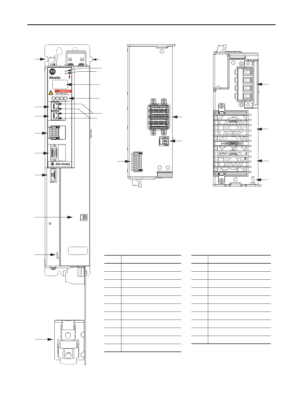
Single-axis Inverter, Front View
(2198-S086-ERS4 module is shown)
Single-axis Inverter, Top View
(2198-S086-ERS4 module is shown)
Single-axis Inverter, Bottom View
(2198-S086-ERS4 module is shown)
Item Description Item Description
1 Motor cable clamp 12 LCD display
2 Tie-wrap bracket for feedback cable 13 Navigation pushbuttons
3 Motor brake (BC) connector 14 Link speed status indicators
4 Motor feedback (MF) connector 15 Link/Activity status indicators
5 Universal feedback (UFB) connector 16 Safe torque-off (STO) connector
6 Digital inputs (IOD) connector 17 DC bus (DC) connector
7 Ethernet (PORT1) RJ45 connector 18 24V control input power (CP) connector
8 Ethernet (PORT2) RJ45 connector 19 Motor power (MP) connector
9 Zero-stack mounting tab/cutout 20 Cooling fans
10 Module status indicator 21 Ground terminal
11 Network status indicator

Table of Contents

Other manuals for Allen-Bradley Kinetix 5700 Series

Questions and Answers:

Question and Answer IconNeed help?

Do you have a question about the Allen-Bradley Kinetix 5700 Series and is the answer not in the manual?

Allen-Bradley Kinetix 5700 Series Specifications

General IconGeneral
BrandAllen-Bradley
ModelKinetix 5700 Series
CategoryServo Drives
LanguageEnglish

Related product manuals