96 Rockwell Automation Publication 2198-UM002G-EN-P - February 2019
Chapter 4 Connector Data and Feature Descriptions
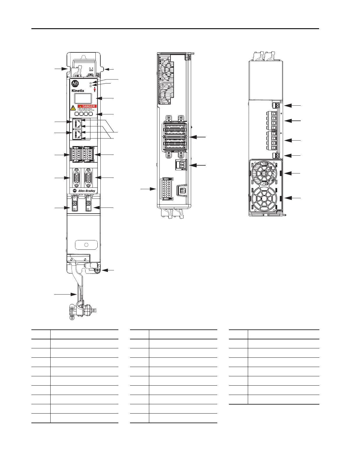
Figure 57 - Dual-axis Inverter Features and Indicators
Item Description Item Description Item Description
1 Motor cable clamp with spacers 10 Ethernet (PORT2) RJ45 connector 19 DC bus (DC) connector
2 Ground terminal 11 Zero-stack mounting tab/cutout 20 24V control input power (CP) connector
3 Motor feedback (MF) connector - A 12 Module status indicator 21 Motor brake (BC) connector - A
4 Motor feedback (MF) connector - B 13 Network status indicator 22 Motor power (MP) connector - A
5 Universal feedback (UFB) connector - A 14 LCD display 23 Motor power (MP) connector - B
6 Universal feedback (UFB) connector - B 15 Navigation pushbuttons 24 Motor brake (BC) connector - B
7 Digital inputs (IOD) connector - A 16 Link speed status indicators 25 Cooling fan
8 Digital inputs (IOD) connector - B 17 Link/Activity status indicators
9 Ethernet (PORT1) RJ45 connector 18 Safe torque-off (STO) connector
22
12
9
17
10
14
13
16
2
11
11
8
20
19
25
15
24
21
3
4
6
5
1
23
25
18
UFB-A
UFB-B
D+
D-
D+
D-
MF-A
MF-B
2
1
DC+
DC–
24V–
24V+
W-B V-B U-B
MBRK-A
– +
W-A V-A U-A
MBRK-B
– +
MOD–
NET–
5700
1
2
3
4
5
6
7
8
9
10
1
2
3
4
5
6
7
8
9
10
1
2
3
4
5
6
7
8
9
10
11
12
13
14
15
16
1
I/O-A
6
510
1
I/O-B
6
510
19
8
16
SB+/NC
NC
S1A
SCA
S2A
SB-
NC
NC
7
Dual-axis Inverter, Front View
(2198-D006-ERS4 module is shown)
Dual-axis Inverter, Top View
(2198-D006-ERS4 module is shown)
Dual-axis Inverter, Bottom View
(2198-D006-ERS4 module is shown)
 Loading...


