108 Rockwell Automation Publication 2094-UM002G-EN-P - August 2016
Chapter 5 Connect the Kinetix 6200 and Kinetix 6500 Drive System
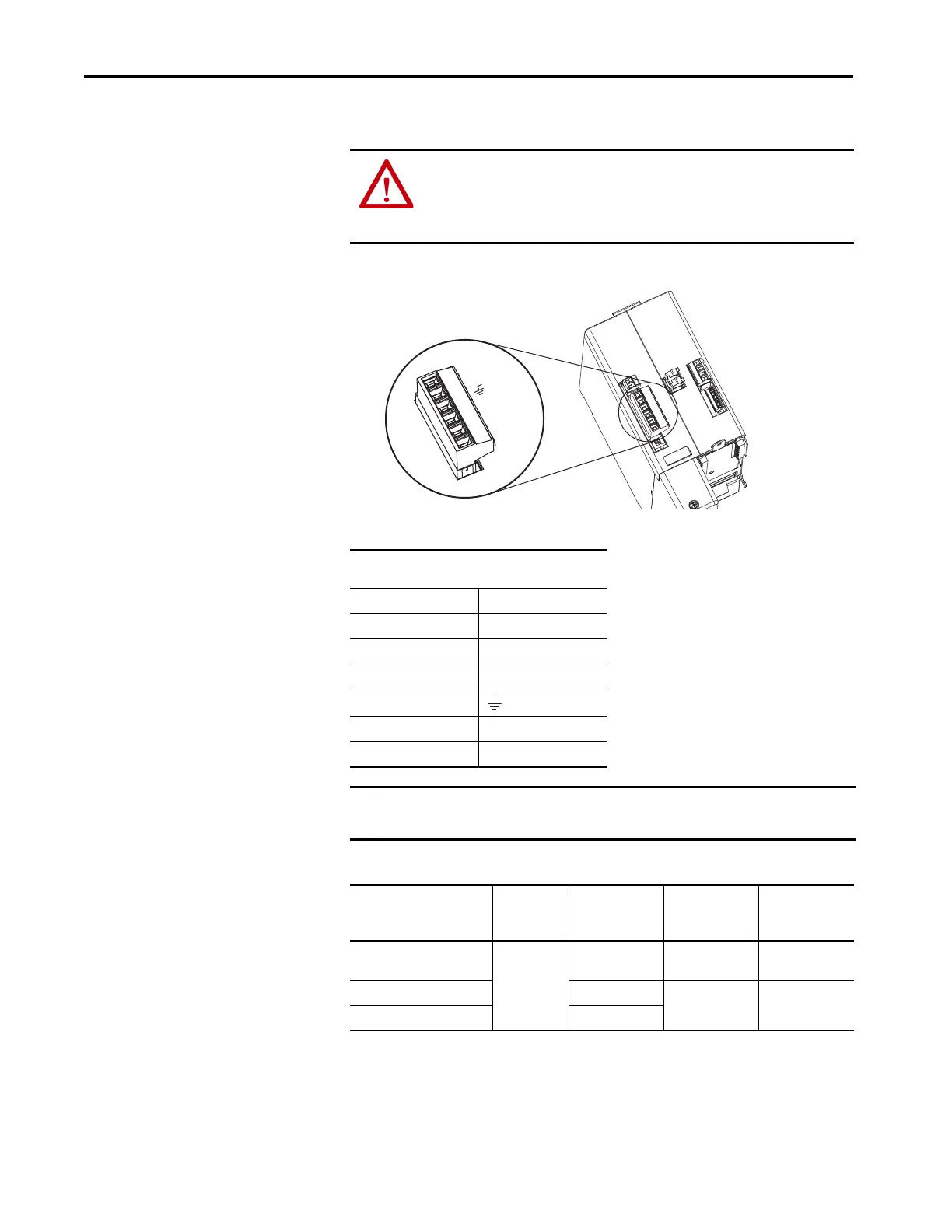
This example applies to a common-bus follower IAM power module.
Figure 57 - IAM Power Module (IPD connector)
Table 60 - Input Power (IPD) Connections
Table 61 - Termination Specifications
ATTENTION: Make sure the common-bus power connections are correct
when wiring the IPD connector plug and that the plug is fully engaged in the
module connector. Incorrect wiring/polarity or loose wiring can cause
explosion or damage to equipment.
Bulletin 2094
IAM Power Module, Top View
IPD Connector
(IAM or follower IAM module)
IPD Pin Signal
6N.C.
5N.C.
4N.C.
3
2DC+
1DC-
IMPORTANT Do not connect three-phase input power to the common-bus follower IAM
module.
IAM Module Cat. No. Input VAC
Recommended
Wire Size
mm
2
(AWG)
Strip Length
mm (in.)
Torque Value
N•m (lb•in)
2094-BC01-Mxx-M
2094-BC02-M02-M
460V AC
2.5 (14) 10 (0.38)
1.2…1.5
(10.6…13.2)
2094-BC04-M03-M 6 (10)
16 (0.63)
2.4…3.0
(21.6…26.5)
2094-BC07-M05-M 30 (3)

 Loading...


