172 Rockwell Automation Publication 2094-UM002G-EN-P - August 2016
Chapter 7 Configure and Start the Kinetix 6500 Drive System
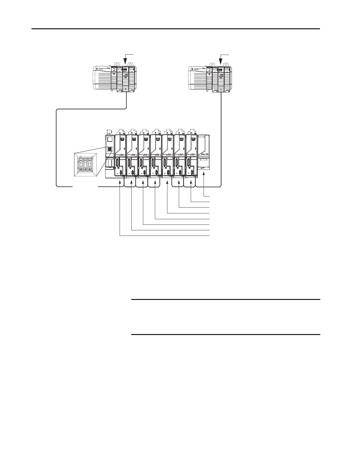
Figure 91 - Node Addressing Example 2
In this example, EtherNet/IP module 1 controls axes 1…4 and module 2
controls axes 5…7. The slot-filler module is not assigned an IP address, but the
system identifies it with a slot location.
You can mount the two EtherNet/IP modules in two separate ControlLogix
chassis (as shown) or you can mount them in the same chassis.
192.168.1.8 = Slot-filler module slot location
192.168.1.7 = Control module (AM axis 7) IP address
192.168.1.6 = Control module (AM axis 6) IP address
192.168.1.5 = Control module (AM axis 5) IP address
192.168.1.4 = Control module (AM axis 4) IP address
192.168.1.3 = Control module (AM axis 3) IP address
192.168.1.2 = Control module (AM axis 2) IP address
192.168.1.1 = Control module (IAM axis 1) IP address
Kinetix 6500 Drive System
(8-axis power rail)
1595J-M8CBJM-x
(shielded) Ethernet Cable
ControlLogix Platform
1756-ENxT EtherNet/IP Module 1
1756-ENxT EtherNet/IP Module 2
ControlLogix Platform
Base node address
set to 001.
IMPORTANT Slot-filler modules must be used to fill any unoccupied slot on the power
rail; however, you can replace slot-filler modules with AM power modules or
the 2094-BSP2 shunt module (maximum one 2094-BSP2 shunt module per
power rail).

 Loading...


