Rockwell Automation Publication 2094-UM002G-EN-P - August 2016 195
Configure and Start the Kinetix 6500 Drive System Chapter 7
6. Determine your need for a hardware enable input at IOD-41 on the I/O
connector.
Digital input 1 (IOD-41) is configured as Enable in the Logix Designer
application by default. You may have changed that on page 181
.
7. Apply Hardware Enable Input signal for the axis you are tuning.
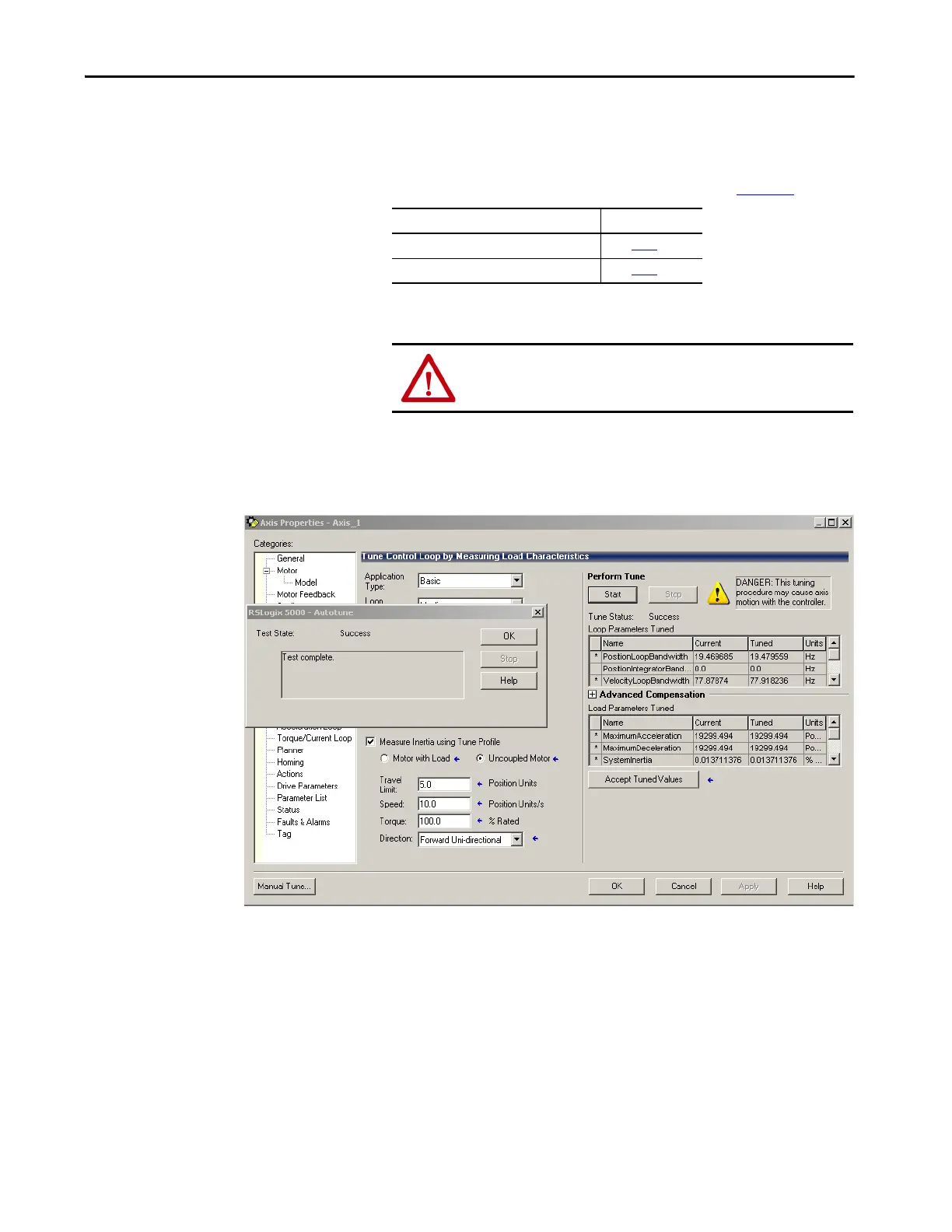
8. Click Start.
The RSLogix - Autotune dialog box opens. When the test completes,
the Test State changes from Executing to Success.
Tuned values populate the Loop and Load parameter tables. Actual
bandwidth values (Hz) depend on your application and may require
adjustment once motor and load are connected.
9. Click OK to close the RSLogix 5000 - Autotune dialog box.
10. Click OK to close the Axis Properties dialog box.
If Digital Input 1 is configured as Then
Enable Go to step 7
.
Unassigned Go to step 8
.
ATTENTION: To avoid personal injury or damage to equipment,
apply 24V ENABLE signal only to the axis you are tuning.

 Loading...


