Publication 1764-UM001B-EN-P - April 2002
Specifications A-5
IMPORTANT
The relay current must stay within the limits defined
in Tables A.5 and A.6.
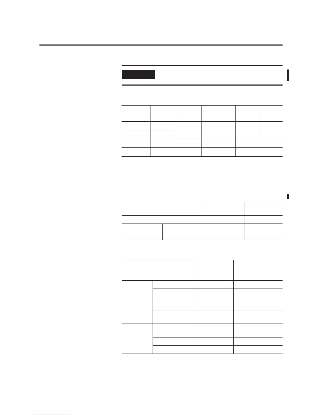
Table A.5 Relay Contact Rating Table 1764-24AWA, -24BWA, -28BXB
Maximum
Volts
Amperes Amperes
Continuous
Voltamperes
Make Break Make Break
240V ac 7.5A 0.75A 2.5A 1800VA
180VA
(2)
(2) The total load controlled by the 1764-24AWA and 1764-24BWA is limited to 1440VA (break).
120V ac 15A 1.5A
125V dc
0.22A
(1)
(1) For dc voltage applications, the make/break ampere rating for relay contacts can be determined by dividing 28
VA by the applied dc voltage. For example, 28 VA/48V dc = 0.58A. For dc voltage applications less than 14V, the
make/break ratings for relay contacts cannot exceed 2A.
1.0A 28VA
24V dc
1.2A
(1)
2.0A 28VA
Table A.6 Output Specifications - Maximum Continuous Relay Current
Specification 1764-24AWA,
-24BWA
1764-28BXB
Current per Common 8A 8A
Current per
Controller
at 150V Maximum 24A 18A
at 240V Maximum 20A 18A
Table A.7 1764-28BXB FET Output Specifications
Specification General
Operation
(Outputs 2 thru 7)
High Speed
Operation
(1)
(Outputs 2 and 3 Only)
User Supply
Voltage
minimum 20.4V dc 20.4V dc
maximum 26.4V dc 26.4V dc
On-State
Voltage Drop
at maximum load
current
1V dc Not Applicable
at maximum surge
current
2.5V dc Not Applicable
Current Rating
per Point
maximum load 1A at 55°C (131°F)
1.5A at 30°C (86°F)
100 mA
minimum load 1.0 mA 10 mA
maximum leakage 1.0 mA 1.0 mA

 Loading...


