3-60 Programming and Parameters
Enhanced Program Group (continued)
E248 [Enh Control Word]
Allows control of positioning and other functions via parameter control for use over comms. The
functions replicate the digital input options and function in the same way. For additional information
refer to Appendix
F.
Important: The Find Home and Position Redefine bits must be returned to 0 following the homing
routine and before starting the drive.
Values Default: 0
Min/Max: 0/1
Display: 1
Bit 0 “Home Limit” In Positioning mode, this indicates the drive is at the home
position.
1 “Find Home” When set, the next start command causes the drive to find
home. Set this bit to 0 after completing the homing routine.
2 “Hold Step” In Positioning mode, this input over-rides other inputs and
causes the drive to remain at its current step (running at zero
speed once it reaches its position) until released.
3 “Pos Redefine” In Positioning mode, this input resets the home position to the
current position of the machine. Set this bit to 0 after
completing the homing routine.
4 “Sync Enable” Must be used in order to hold the existing frequency when
Sync Time is set to enable speed synchronization. When this
bit is reset to zero the drive will accelerate to the new
commanded frequency based on E214
[Sync Time] setting.
5 “Traverse Disable” When set the traverse function will be disabled.
6 “Logic In 1” This provides an identical function as the “Logic In1” Digital
Input option. This bit is logically ORed with a digital input
A051
- A054 set to option 23 “Logic In1”. It can be used to
move through the Step-Logic functions (speed or position) via
comms control without requiring actual digital input
transitions.
7 “Logic In 2” This provides and identical function as the “Logic In2” Digital
Input option. This bit is logically ORed with a digital input
A051
- A054 set to option 24 “Logic In2”. It can be used to
move through the Step-Logic functions (speed or position) via
comms control without requiring actual digital input
transitions.
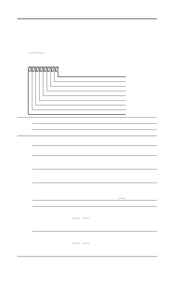
1 = Input Present, 0 = Input Not Present
Home Limit Bit 0
Find Home Bit 1
Hold Step Bit 2
Pos Redefine Bit 3
Sync Enable Bit 4
Traverse Disable Bit 5
Logic In 1 Bit 6
Logic In 2 Bit 7
 Loading...


