Installation/Wiring 1-5
Input Power Conditioning
The drive is suitable for direct connection to input power within the rated
voltage of the drive (see Appendix
A). Listed in Table 1.B are certain
input power conditions which may cause component damage or
reduction in product life. If any of the conditions exist, as described in
Table 1.B
, install one of the devices listed under the heading Corrective
Action on the line side of the drive.
Important: Only one device per branch circuit is required. It should be
mounted closest to the branch and sized to handle the total
current of the branch circuit.
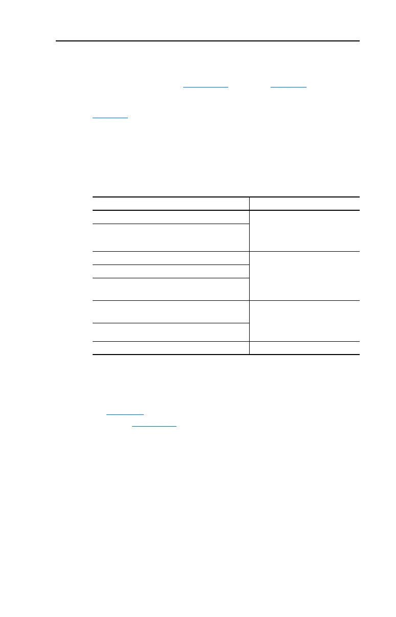
Table 1.B Input Power Conditions
Input Power Condition Corrective Action
Low Line Impedance (less than 1% line reactance) • Install Line Reactor
(2)
• or Isolation Transformer
• or Bus Inductor – 5.5 & 11 kW
(7.5 & 15 HP) drives only
(2)
Refer to Appendix B for accessory ordering information.
Greater than 120 kVA supply transformer
Line has power factor correction capacitors • Install Line Reactor
• or Isolation Transformer
Line has frequent power interruptions
Line has intermittent noise spikes in excess of
6000V (lightning)
Phase to ground voltage exceeds 125% of normal
line to line voltage
• Remove MOV jumper to ground.
• or Install Isolation Transformer
with grounded secondary if
necessary.
Ungrounded distribution system
240V open delta configuration (stinger leg)
(1)
(1)
For drives applied on an open delta with a middle phase grounded neutral system, the
phase opposite the phase that is tapped in the middle to the neutral or earth is
referred to as the “stinger leg,” “high leg,” “red leg,” etc. This leg should be identified
throughout the system with red or orange tape on the wire at each connection point.
The stinger leg should be connected to the center Phase B on the reactor. Refer to
Table B.D for specific line reactor part numbers.
• Install Line Reactor
 Loading...


