1-20 Installation/Wiring
Hardware Enable Circuitry
I/O Terminal 01 is always a stop input. The status of this input is
interpreted by drive software. If the application requires the drive to be
disabled without software interpretation, a hardware enable
configuration can be utilized. This is done by removing the ENBL
enable jumper and wiring the enable input to I/O Terminal 1 (see below).
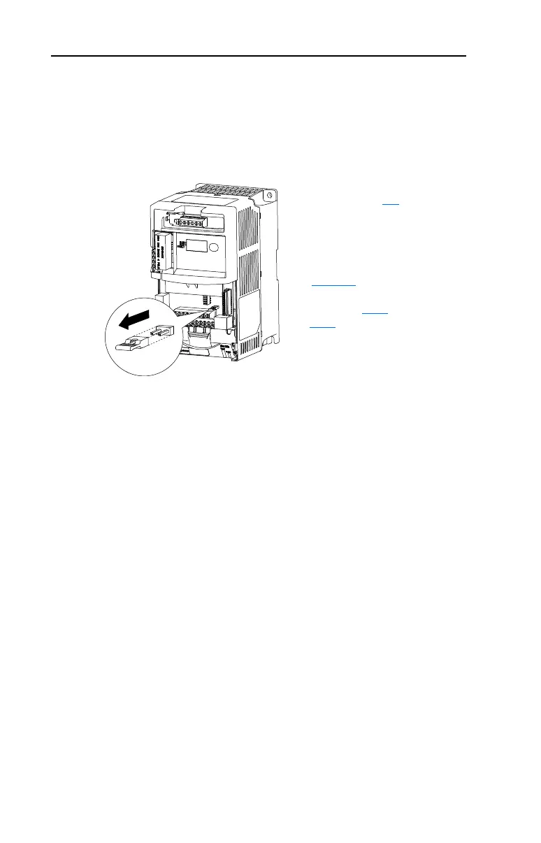
1. Remove drive cover as
described on page 1-1
.
2. Locate and remove the Enable
Jumper on the Main Control Board
(see diagram).
3. Wire Enable to I/O Terminal 1
(see Table 1.I). The drive will
always coast to a stop regardless of
the settings of P036
[Start Source]
and P037
[Stop Mode].
4. If I/O Terminal 01 is used as
hardware enable and 3-wire control
is needed, program one of the
digital inputs for the desired stop
mode.

 Loading...


