Installation/Wiring 1-21
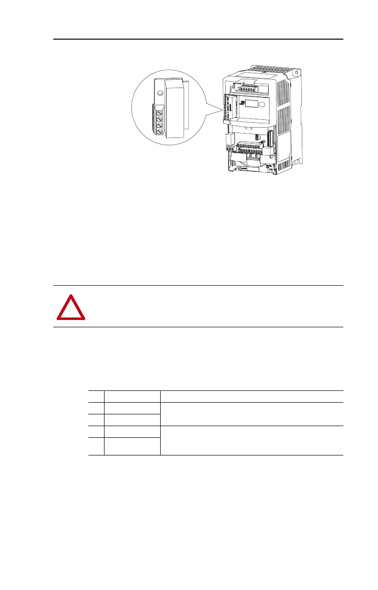
User Installed DriveGuard Safe-Off Option (Series B)
The DriveGuard Safe-Off Option (Series B) board, when used with
suitable safety components, provides protection according to EN ISO
13849-1:2008+AC:2009; Performance Level d (Safety Category 3) for
safe off and protection against restart. The PowerFlex safe off option is
just one safety control system. All components in the system must be
chosen and applied correctly to achieve the desired level of operator
safeguarding. Refer to the DriveGuard Safe-Off Option (Series B) User
Manual, publication PFLEX-UM003… for detailed installation
information.
Important: When using the DriveGuard Safe-Off Option (Series B)
with the drive in an IP30/NEMA 1/UL Type 1 installation,
only use low voltage Class 2 circuits.
Table 1.K Safe-Off Option Terminal Description
1
2
3
4
ATTENTION: Hazard of injury exists due to electric shock. Only
install a Series B or greater DriveGuard Safe-Off Option in a PowerFlex
40P Drive.
No. Signal Description
4 24V Common
Connections for user supplied power to energize coil.
3 +24V DC
2 Common - N.C. Normally closed contacts for monitoring relay status.
Maximum Resistive Load: 250V AC / 30V DC / 50 VA / 60 Watts
Maximum Inductive Load: 250V AC / 30V DC / 25 VA / 30 Watts
1 Monitor - N.C.

 Loading...


