Rockwell Automation Publication 750-IN100B-EN-P - July 2017 109
Power Wiring Chapter 5
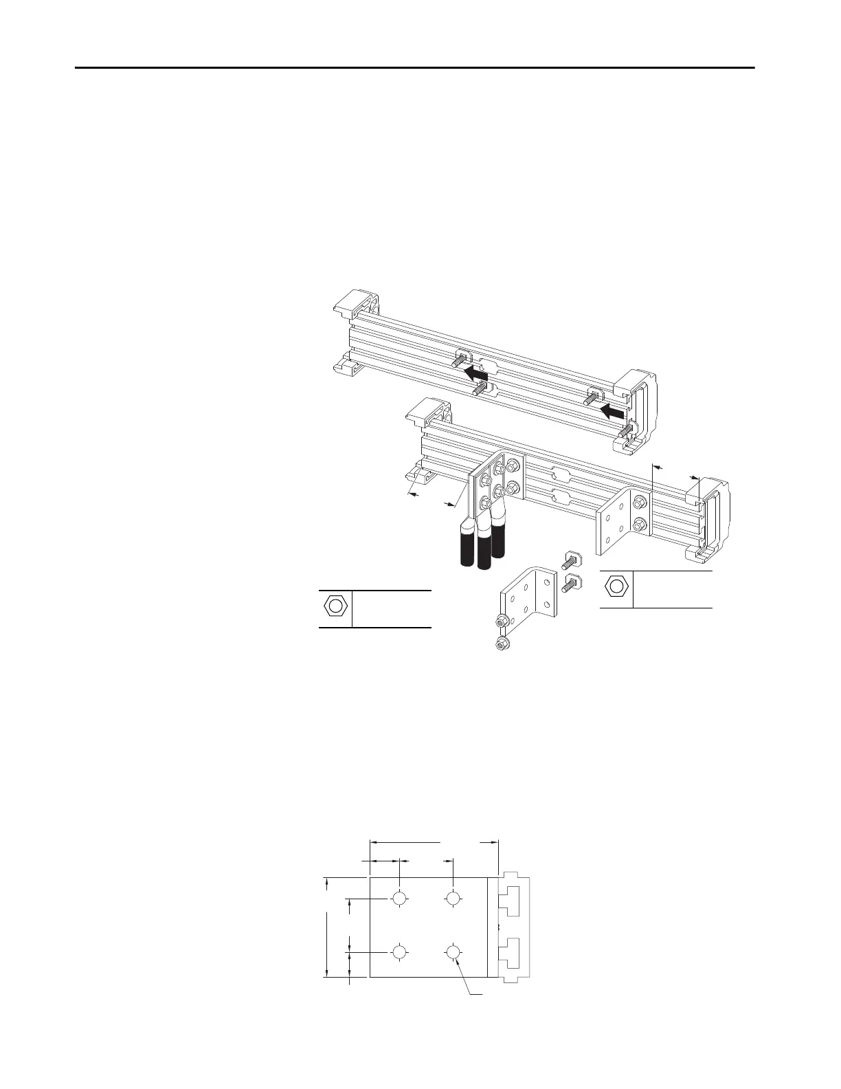
L-Bracket Connections
Power cable connections in entry and exit wire bay are made using L-brackets.
The M10 hardware that is required to fasten the L-brackets to the slotted bus
bar is provided. Wires with appropriate barrel lugs can be bolted to both sides
of the L-brackets if necessary. Up to four conductors can be attached to each L-
bracket. Attach the conductors to the L-brackets using M12 or 0.5 in. diameter
bolts, nuts, and washers. Bellville spring washers, or equivalent, are
recommended. Keep the L-bracket connections at least 51 mm (2 in.) away
from the ends of the slotted bus bar.
Additional Power Terminal L-Brackets
PowerFlex 755T entry and exit wire bays come equipped with L-brackets. If an
application requires additional L-brackets, kit number 20-750-MLBRKT-
F8M is available. Each kit contains three L-brackets and mounting hardware.
Figure 58 - L-Bracket Approximate Dimensions
Cable Connections
Customer-supplied M12 hardware.
M10
15 mm
38 N•m (336 lb•in)
M12
19 mm
38 N•m (336 lb•in)
46.0 mm
(1.81 in.)
25.5 mm
(1.04 in.)
85.1 mm
(3.35 in.)
110.0 mm
(0.70 in.)
(0.43 in.)

 Loading...


