150 Rockwell Automation Publication 750-IN100B-EN-P - July 2017
Chapter 6 I/O Wiring
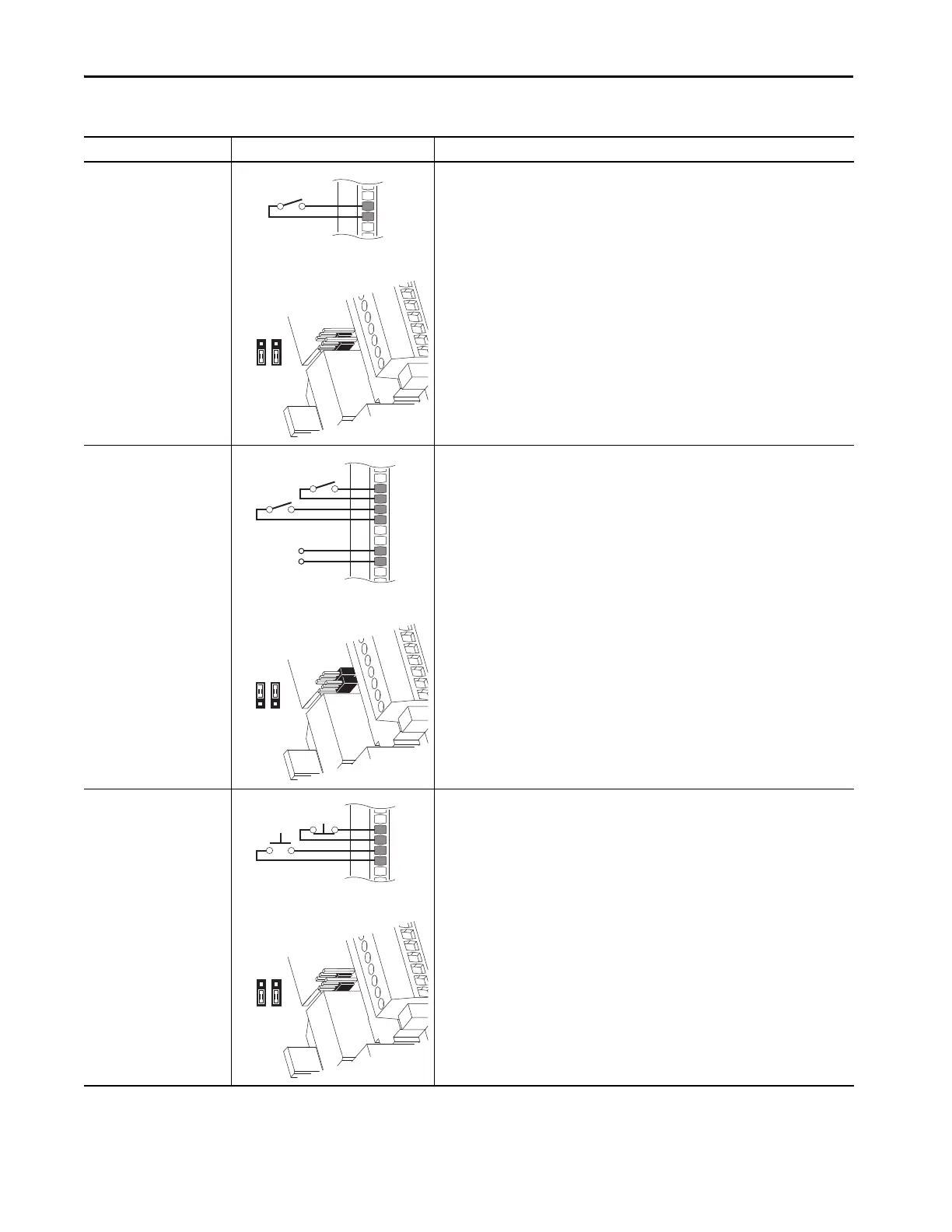
2-Wire Control Non-
Reversing
24V DC internal supply
11-Series I/O Module TB1
• Set Direction Mode
Port 10/11:930 [Direction Mode] = 2 ‘Rev Disable’
•Set Selection
Port 00:120 [DI M Run] = Port nn:1 [Dig In Sts], bit 0 = Input 0 (11-Series I/O Module)
• View Results
Port nn:1 [Dig In Sts] (11-Series I/O Module)
Port 10/11:354 [Motor Side Sts 1]
2-Wire Control Reversing
External 24 volt supply
20-750-1132C-2R
20-750-1133C-1R2T
11-Series I/O Module TB1
• Set Direction Mode
Port 10/11:930 [Direction Mode] = 0 ‘Unipolar’
•Set Selection
Port 00:121 [DI M Run Forward] = Port nn:1 [Dig In Sts], bit 0 = Input 0 (11-Series I/O
Module)
Port 00:122 [DI M Run Reverse] = Port nn:1 [Dig In Sts], bit 1 = Input 1 (11-Series I/O
Module)
• View Results
Port nn:1 [Dig In Sts] (11-Series I/O Module)
Port 10/11:354 [Motor Side Sts 1]
3-Wire Control
Internal supply
11-Series I/O Module TB1
•Set Selection
Port 00:108 [DI M Stop] = Port nn:1 [Dig In Sts], bit 0 = Input 0 (11-Series I/O Module)
Port 00:117 [DI M Start] = Port nn:1 [Dig In Sts], bit 1 = Input 1 (11-Series I/O Module)
• View Results
Port nn:1 [Dig In Sts] (11-Series I/O Module)
Port 10/11:354 [Motor Side Sts 1]
Table 28 - 11-Series I/O Module TB1 Wiring Examples (continued)
Input/Output Connection Example Required Parameter Changes
Di0P
P3
Di0P
Di1P
Ip
Ic
+24V
Common
Run Fwd
Run Rev
Di0P
Di1P
P3

 Loading...


