152 Rockwell Automation Publication 750-IN100B-EN-P - July 2017
Chapter 6 I/O Wiring
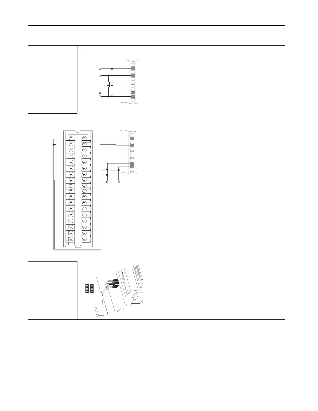
Digital Input
PLC Output Module
External supply
11-Series I/O Module TB1
•Set Selection
Port 00:108 [DI M Stop] = Port nn:1 [Dig In Sts], bit 0 = Input 0 (11-Series I/O Module)
Port 00:117 [DI M Start] = Port nn:1 [Dig In Sts], bit 1 = Input 1 (11-Series I/O Module)
• View Results
Port nn:1 [Dig In Sts] (11-Series I/O Module)
Port 10/11:354 [Motor Side Sts 1]
Note: Pull down resistors may be required by some PLC interfaces.
OR
Table 28 - 11-Series I/O Module TB1 Wiring Examples (continued)
Input/Output Connection Example Required Parameter Changes
+120V AC/24V DC
Control from
Prog. Controller
10k Ohm, 2 Watt
(See Note)
Ip
Ic
12
34
5
6
78
910
1112
1314
1516
1718
1920
2122
2324
2526
2728
2930
31
32
3334
3536
+DC-0
+DC-0
+DC-0
+DC-0
+DC-1
+DC-0
+DC-0
+DC-0
GND-0
Not Used
+DC-1
+DC-1
+DC-1
+DC-1
+DC-1
+DC-1
GND-1
GND-1
OUT-0
OUT-1
OUT-2
OUT-3
OUT-8
OUT-4
OUT-5
OUT-6
OUT-7
Not Used
OUT-9
OUT-10
OUT-11
OUT-12
OUT-13
OUT-14
OUT-15
Not Used
+24V DC
Common
PLC TB
11-Series I/O Module TB1

 Loading...


