160 Rockwell Automation Publication 750-IN100B-EN-P - July 2017
Chapter 6 I/O Wiring
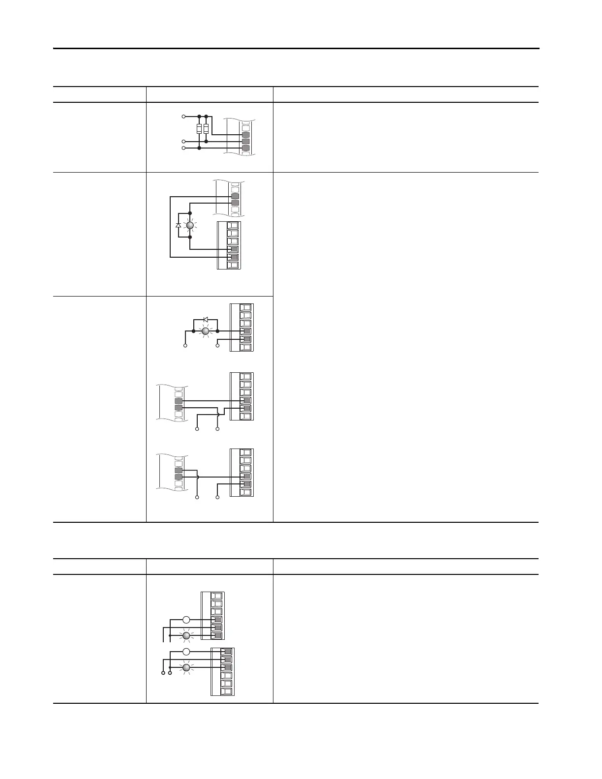
Digital Input
PLC Output Module
22-Series I/O Module TB1
•Set Selection
Port 00:108 [DI M Stop] = Port nn:1 [Dig In Sts], bit 0 = Input 0 (22-Series I/O Module)
Port 00:117 [DI M Start] = Port nn: 1 [Dig In Sts], bit 1 = Input 1 (22-Series I/O Module)
•View Results
Port nn:1 [Dig In Sts] (22-Series I/O Module)
Port 10/11:354 [Motor Side Sts 1]
Digital Output
Internal supply
20-750-2263C-1R2T
22-Series I/O Module TB1
22-Series I/O Module TB2
•Set Selection
Port nn:20 [TO0 Sel] (22-Series I/O Module) = Port 10/11:354 [Motor Side Sts 1], bit 7 =
Faulted
•View Results
Port nn:5 [Dig Out Sts]s (22-Series I/O Module)
Digital Output
External supply
20-750-2263C-1R2T
PLC TB 22-Series I/O Module TB2
Table 34 - 22-Series I/O Module TB1 Wiring Examples (continued)
Input/Output Connection Example Required Parameter Changes
+24V
T1
+24VDC Common
PLC
1756-1B16
IN-0
GND-0
Table 35 - 22-Series I/O Relay Wiring Examples
Input/Output Connection Example Required Parameter Changes
Relay Output
External supply
22-Series I/O Module • Set Selection
Port nn:10 [RO0 Sel] (22-Series I/O Module) = Port 10/11:354 [Motor Side Sts 1], bit 7 =
Faulted
•View Results
Port nn:5 [Dig Out Sts] (22-Series I/O Module)
Power
Source
or
R0NO

 Loading...


