164 Rockwell Automation Publication 750-IN100B-EN-P - July 2017
Chapter 6 I/O Wiring
Cabling
Safety input wiring must be protected against external damage by cable
ducting, conduit, armored cable or other means.
Shielded cable is required.
When installed in a Frame 8 or larger drive, an EMC Core Kit, catalog number
20-750-EMCSSM1-F8, is required.
Feedback Devices
The Safe Speed Monitor option must be used with one of the following
feedback devices.
• Dual Incremental Encoder module, catalog number 20-750-DENC-1
• Universal Feedback module catalog number 20-750-UFB-1
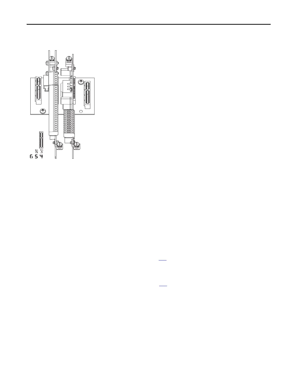
Port Assignment
The Safe Speed Monitor option and the feedback device must be installed on
the same backplane using ports 4, 5, or 6.
When used in an Integrated Motion application, the Safe Speed Monitor
option must be installed in port 06.
Only one safety option module can be installed at a time. Multiple safety
options or duplicate safety option installations are not supported.
Jumper Settings
Ensure the hardware enable jumper (ENABLE) on the main control board is
installed. Refer to page 141
for location. If not installed, the drive will fault
when powered up.
Ensure the safety enable jumper (SAFETY) on the main control board is
removed. Refer to page 142
for location.
Parameter Settings
There are required parameter settings when used with the Universal Feedback
module.
• Set Safe Speed Monitor parameter 28 [Fbk 1 Type] to option 0 ‘Sine/
Cosine.’
• Set Universal Feedback parameter 6 [FB0 Device Sel] to a Sine/Cosine
type device.

 Loading...


