174 Rockwell Automation Publication 750-IN100B-EN-P - July 2017
Chapter 6 I/O Wiring
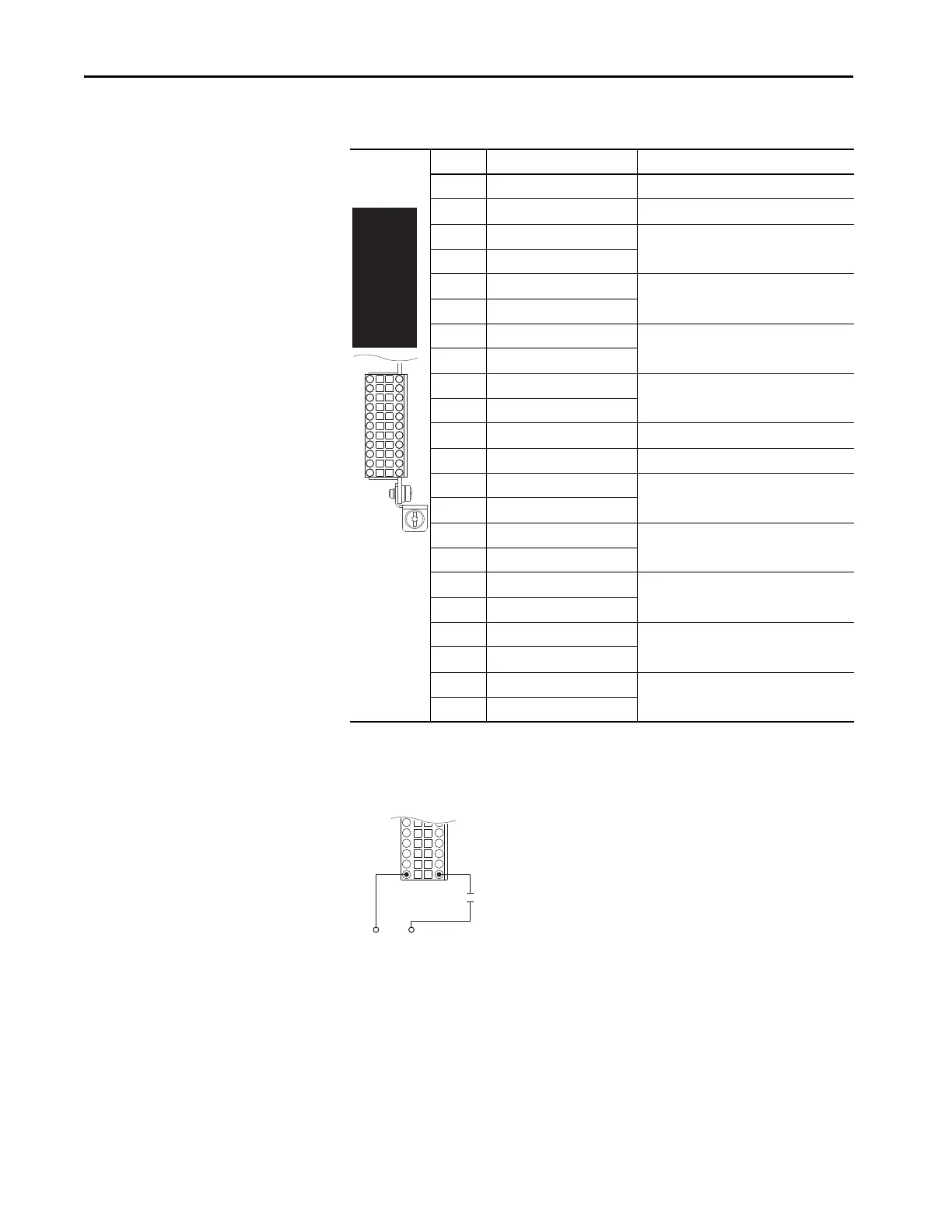
Wiring Examples - Single Incremental Encoder Option Module Connections
Figure 69 - Homing Signal – External Power
Table 62 - Dual Incremental Encoder Terminal Designations
Terminal Name Description
ES +12 or +5 Volt DC Power Power supply for Encoder 0, 250 mA.
EC Common +12V and +5V Encoder 0, common
0A Encoder 0: A Single channel or quadrature A input.
0A- Encoder 0: A (NOT)
0B Encoder 0: B Quadrature B input.
0B- Encoder 0: B (NOT)
0Z Encoder 0: Z Pulse or marker input.
0Z- Encoder 0: Z (NOT)
Sd Encoder Shield Terminating point for wire shields when an EMC
plate or conduit box is not installed.
Sd Encoder Shield
ES +12 or +5 Volt DC Power Power supply for Encoder 1, 250 mA.
EC Common +12V and +5V Encoder 1, common
1A Encoder 1: A Single channel or quadrature A input.
1A- Encoder 1: A (NOT)
1B Encoder 1: B Quadrature B input.
1B- Encoder 1: B (NOT)
1Z Encoder 1: Z Pulse or marker input.
1Z- Encoder 1: Z (NOT)
24 +24 Volt Power source for homing input.
24C Common
Hm Homing Input Captures the AB edge counter.
HmC Homing Input Common
EC
0A-
0B-
0Z-
Sd
EC
1A-
1B-
1Z-
24C
HmC
ES
Home Switch
Common+24V
External Power Supply

 Loading...


