Publication 1747-UM011G-EN-P - June 2008
Installing Your Hardware Components 109
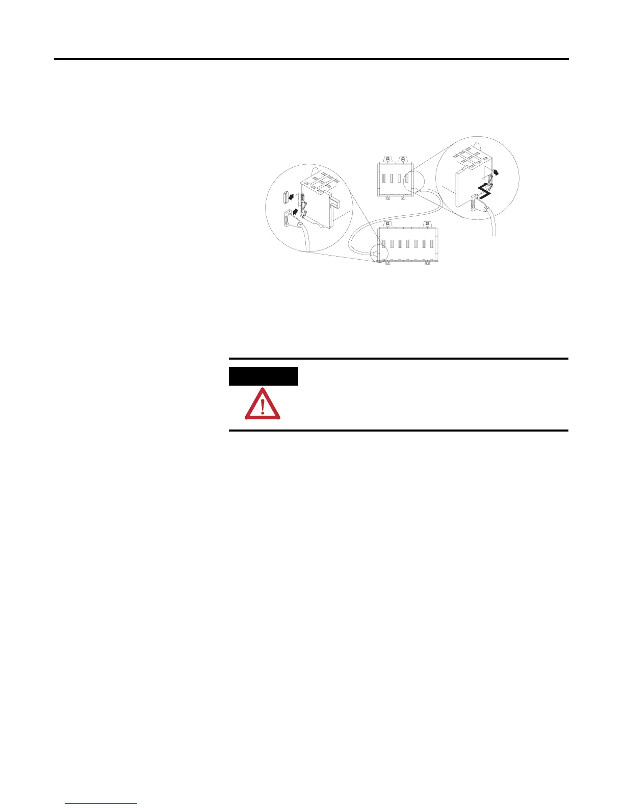
Chassis Connections
To remove the cable, move the tabs on the socket outward and the
connector pops out.
ATTENTION
The expansion cable must always exit the right end of the
chassis with the processor and connect to the left end of the
next I/O chassis.
SLC chassis where
processor will be installed

 Loading...


