Publication 1747-UM011G-EN-P - June 2008
212 RS-232 Communication Interface
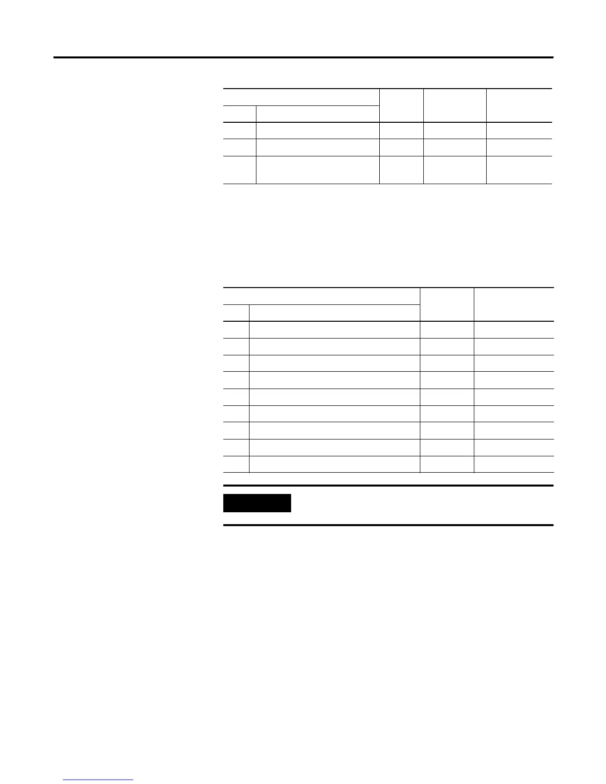
DCE Pinout
Devices such as a modem are DCE. The pinouts on these terminals
are wired to interface with DTE.
7 RTS Request to Send Output 4 4
8 CTS Clear to Send Input 5 5
9 NC No Connection Input 22 (RI Ring
Indicator)
DCE 9 Pinout Signal is Equivalent DCE 25
Pinout
Pin Description
1 DCD Data Carrier Detect Input 8
2 RXD Received Data Input 3
3 TXD Transmitted Data Output 2
4 DTR Data Terminal Ready Output 20
5 COM Common Return (Signal Ground) Shared 7
6 DSR Data Set Ready Input 6
7 RTS Request to Send Output 4
8 CTS Clear to Send Input 5
9 RI Ring Indicator Input 22
IMPORTANT
DCE signal names are viewed from a DTE perspective. For
example, TXD is a DTE output and also a DCE input.
DTE 9 Pinout Signal is Equivalent
DTE 15 Pinout
Equivalent
DTE 25 Pinout
Pin Description

 Loading...


