Publication 1747-UM011G-EN-P - June 2008
RS-232 Communication Interface 211
DCD (Data Carrier Detect) - this is an input signal from the DCE that
indicates a carrier signal is being received and that presumably data is to be
received for forwarding to the DTE connected.
Wiring Connectors for
RS-232 Communication
To connect Allen-Bradley devices with other devices over RS-232, you must
wire the cable connectors so that communication can occur through the
cabling, which provide the interface between devices.
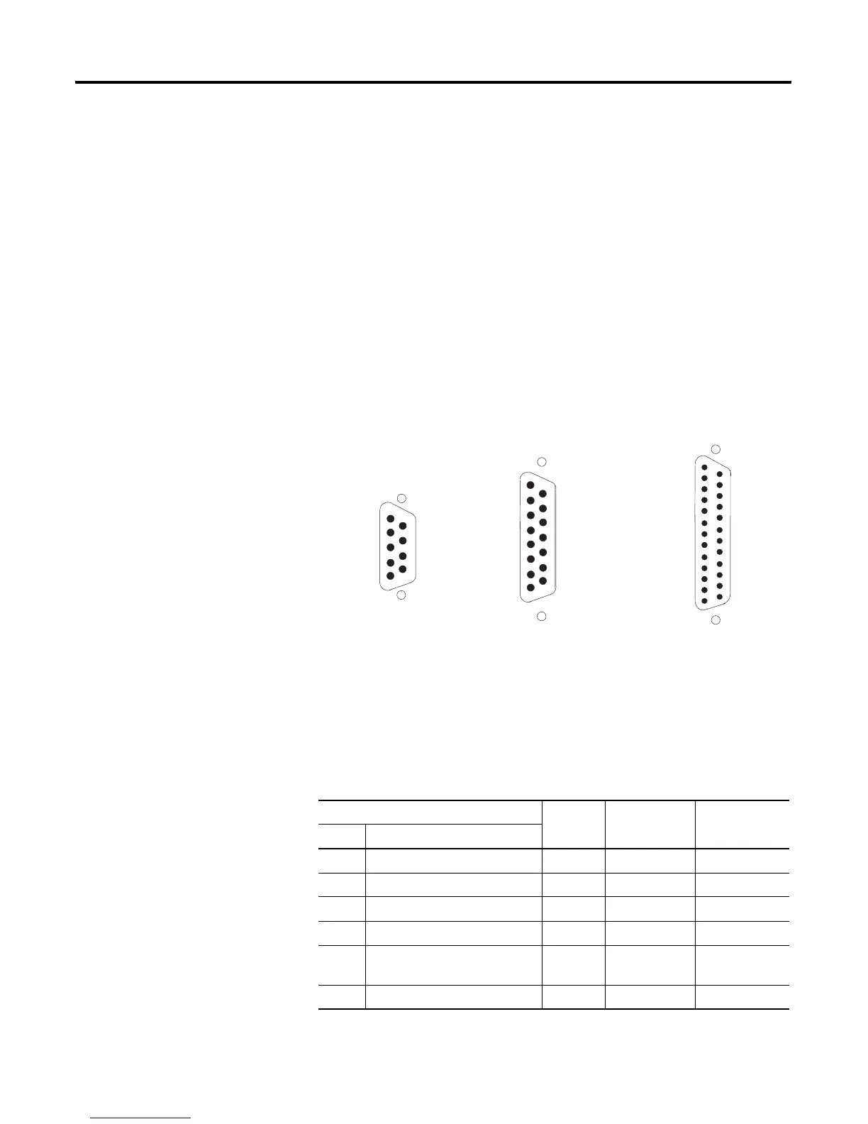
Types of RS-232 Connectors
The figures below show male connectors, and their pinout locations, for
Allen-Bradley devices.
DTE Pinout
Channel 0 is configured as DTE for all SLC 5/03, SLC 5/04, and SLC 5/05
processors. The pinouts are the same as the 9-pin personal computer port.
DTE 9 Pinout Signal is Equivalent
DTE 15 Pinout
Equivalent
DTE 25 Pinout
Pin Description
1 DCD Data Carrier Detect Input 8 8
2 RXD Received Data Input 3 3
3 TXD Transmitted Data Output 2 2
4 DTR Data Terminal Ready Output 11 20
5 COM Common Return (Signal
Ground)
Shared 7 7
6 DSR Data Set Ready Input 6 6
25
24
23
22
21
20
19
18
17
16
15
14
13
12
11
10
9
8
7
6
5
4
3
2
1
8
7
6
5
4
3
2
1
15
14
13
12
11
10
9
5
4
3
2
1
9
8
7
6
9-Pin Connector (male) 15-Pin Connector (male) 25-Pin Connector (male)

 Loading...


