GS910 Series Gigabit Ehternet Unmanaged Switch Installation and User’s Guide
14
AT-GS910/8
Switch
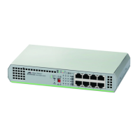
The AT-GS910/8 switch has eight 10/100/1000Base-TX twisted pair ports
on the front panel as shown in Figure 5.
x
Figure 5. AT-GS910/8 Front Panel
The AT-GS910/8 switch has an internal power supply with a single AC
power supply socket on the rear panel as shown in Figure 6.
x
Figure 6. AT-GS910/8 Rear Panel
The AT-GS910/8 switch can be installed on a desktop, mounted on a wall,
or mounted in a 19-inch equipment rack. To mount the switch on a wall,
use the AT-BRKT-J23 wall mount brackets. To install the switch in an
equipment rack, use the AT-RKMT-J08 rack mount brackets.
The AT-BRKT-J23 and AT-RKMT-J08 brackets are not included in
the shipping box. You must purchase them separately.
AT-GS910/8E
Switch
The AT-GS910/8E switch has eight 10/100/1000Base-TX twisted pair
ports on the front panel as shown in Figure 7. The switch is installed on a
desktop only.
x
Figure 7. AT-GS910/8E Front Panel
 Loading...


