Chapter 2: Installation
45
2. Attach the extension to the bracket with the M4x6mm screws using a
Phillips-head screw driver as shown in See Figure 24.
x
Figure 24. Attaching the Extension to the Bracket
3. Turn the switch upside down and place it on a table.
4. Remove the rubber feet from the bottom of the switch using a
Phillips-head screwdriver.
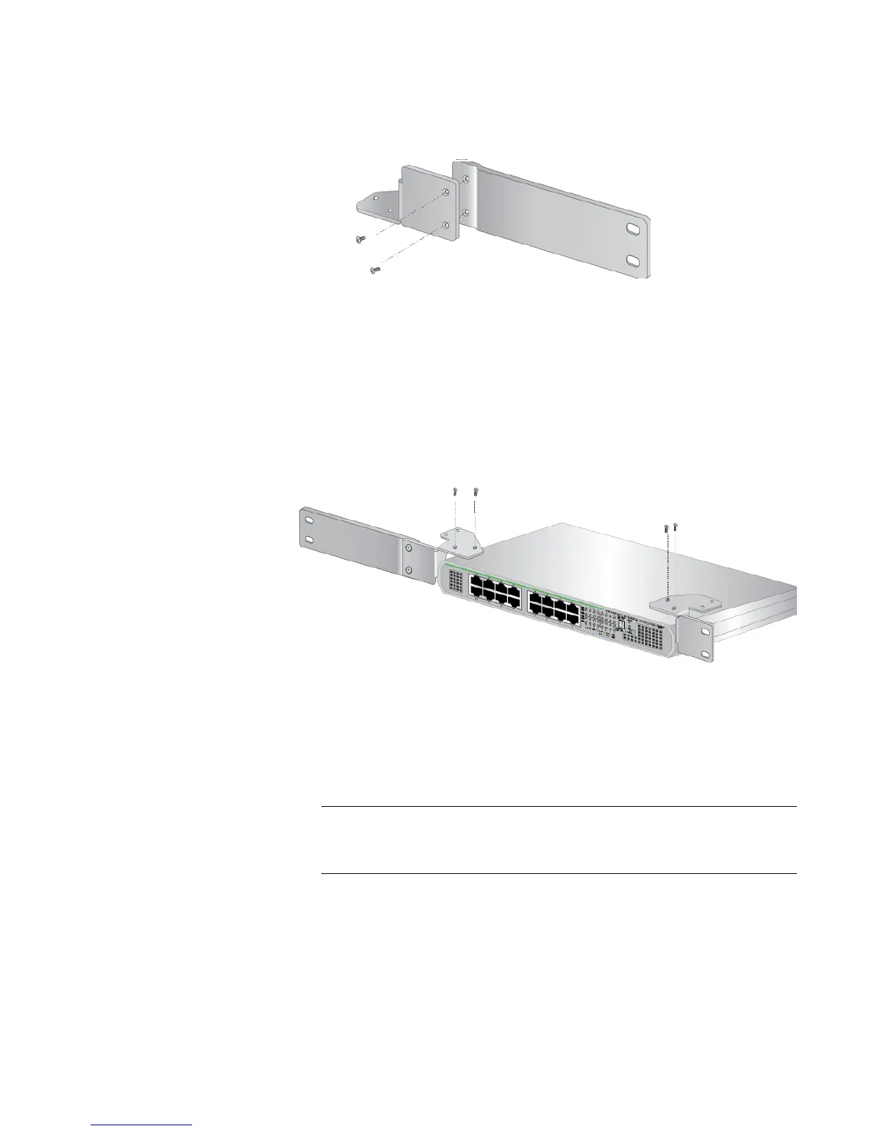
5. Attached the brackets to the switch with the M3x6mm screws using a
Phillips-head screwdriver. See Figure 25.
x
Figure 25. Attaching the Brackets to the Switch
6. Turn the switch over.
7. Mount the switch in a standard 19-inch equipment rack with four
equipment rack screws as shown in Figure 26 on page 46.
The screws for an equipment rack are not included in the shipping
box.

 Loading...