Chapter 2: Installation
47
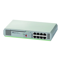
3. Attach the brackets to the switch with the M3x6mm screws using a
Phillips-head screwdriver. See Figure 28.
x
Figure 28. Attaching the Brackets to the Switch
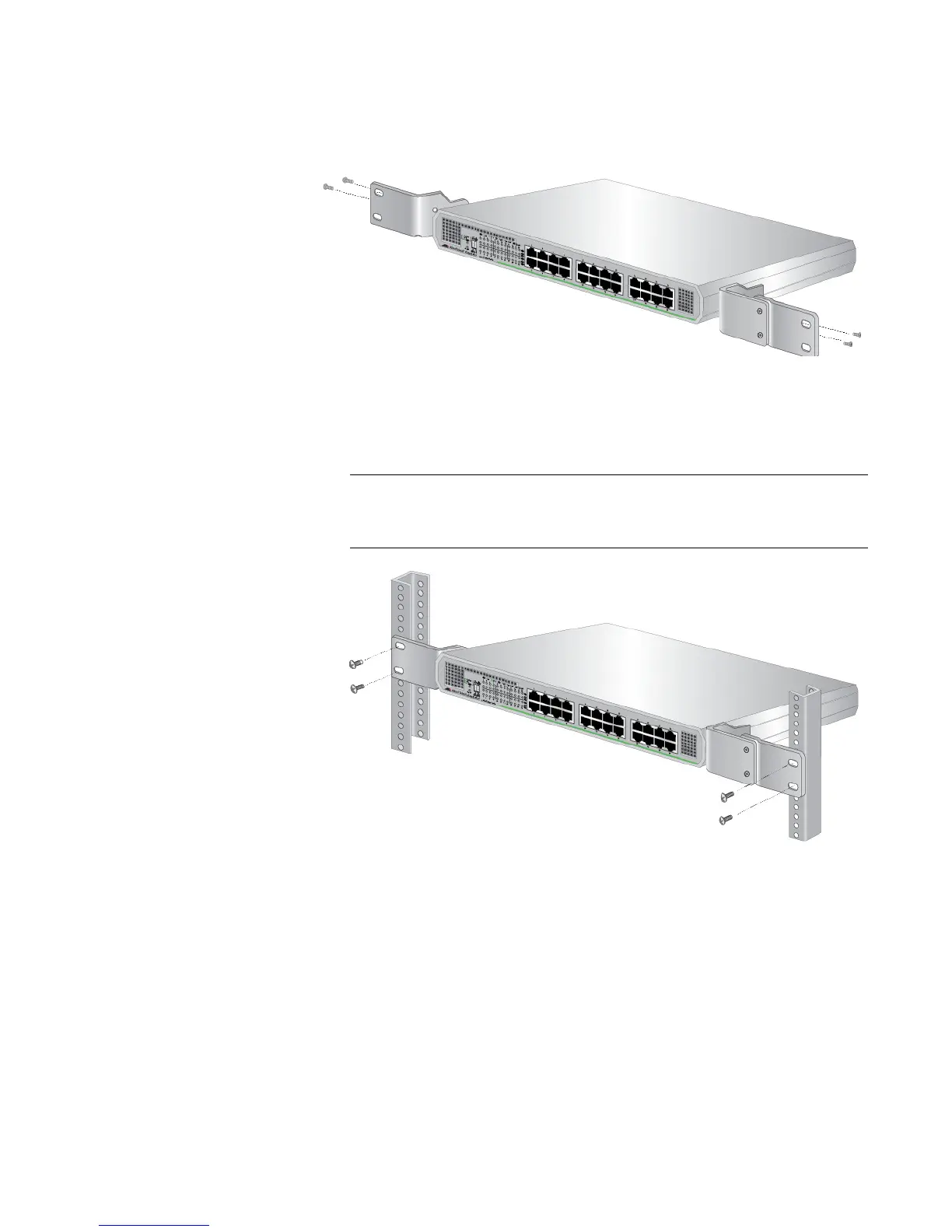
4. Mount the switch in a standard 19-inch equipment rack with four
equipment rack screws as shown in Figure 29.
The screws for an equipment rack are not included in the shipping
box.
x
Figure 29. Attaching the Switch to an Equipment Rack
5. Proceed to “Cabling the Switch” on page 48.
 Loading...


