GS910 Series Gigabit Ehternet Switch Installation and User’s Guide
62
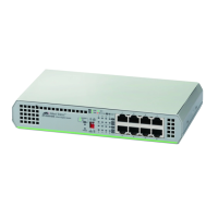
4. Attach the cable bracket to the unit that you assembled in Step 3 with
M4x6mm screws using a Phillip-head screw driver as shown in
Figure 36.
Figure 36. Attaching Cable Tray to Plates
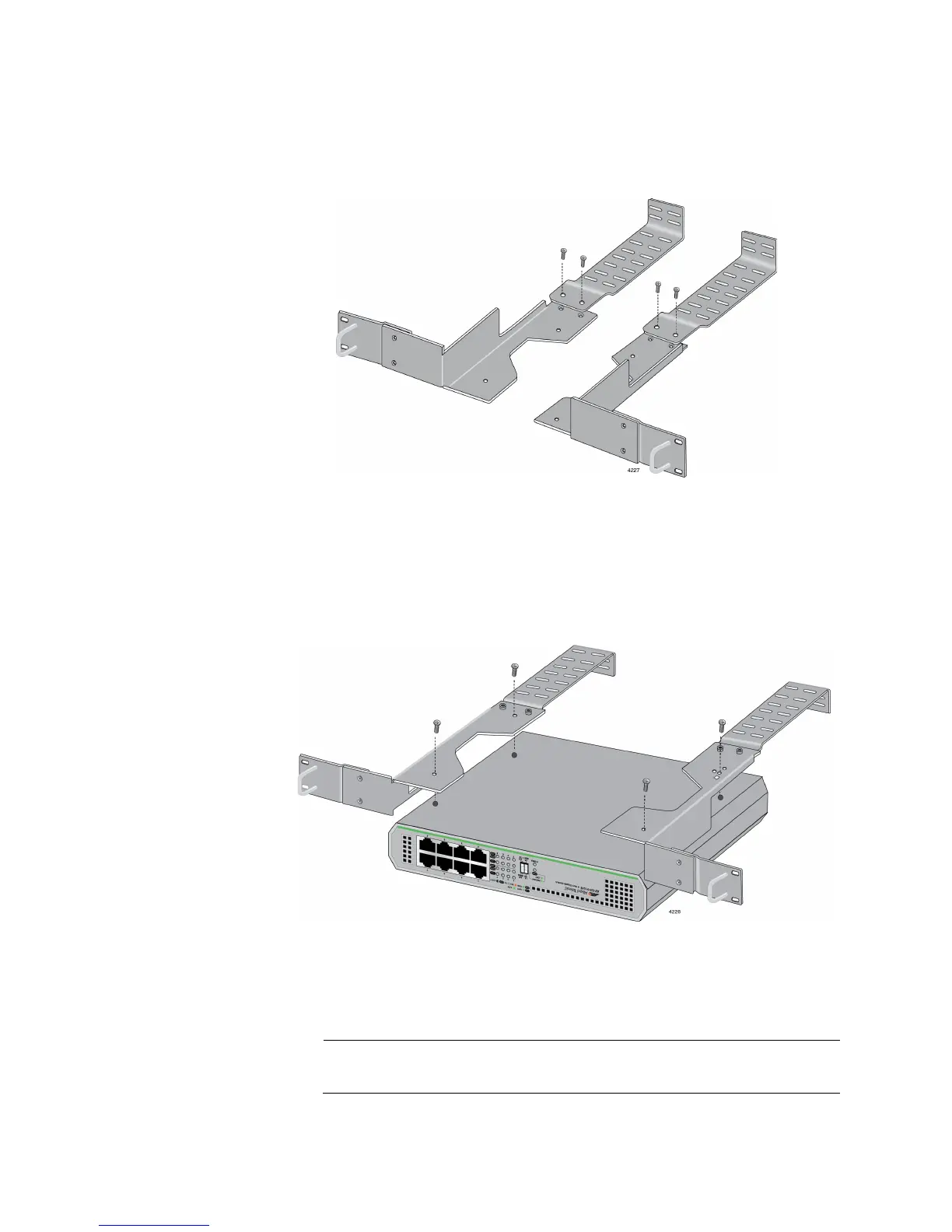
5. Turn the switch over and place it on the work table.
6. Attach the units in Step 4 to the switch with M3x6mm screws using a
Phillip-head screw driver as shown in Figure 37.
Figure 37. Attaching the Plates to the Switch
7. Mount the switch in a standard 19-inch equipment rack with four
equipment rack screws as shown in Figure 38 on page 63.
The screws are not included in the AT-RKMT-J08 rack mount kit.
 Loading...


