BOOM BARRIER BV5868 2525
SETUP
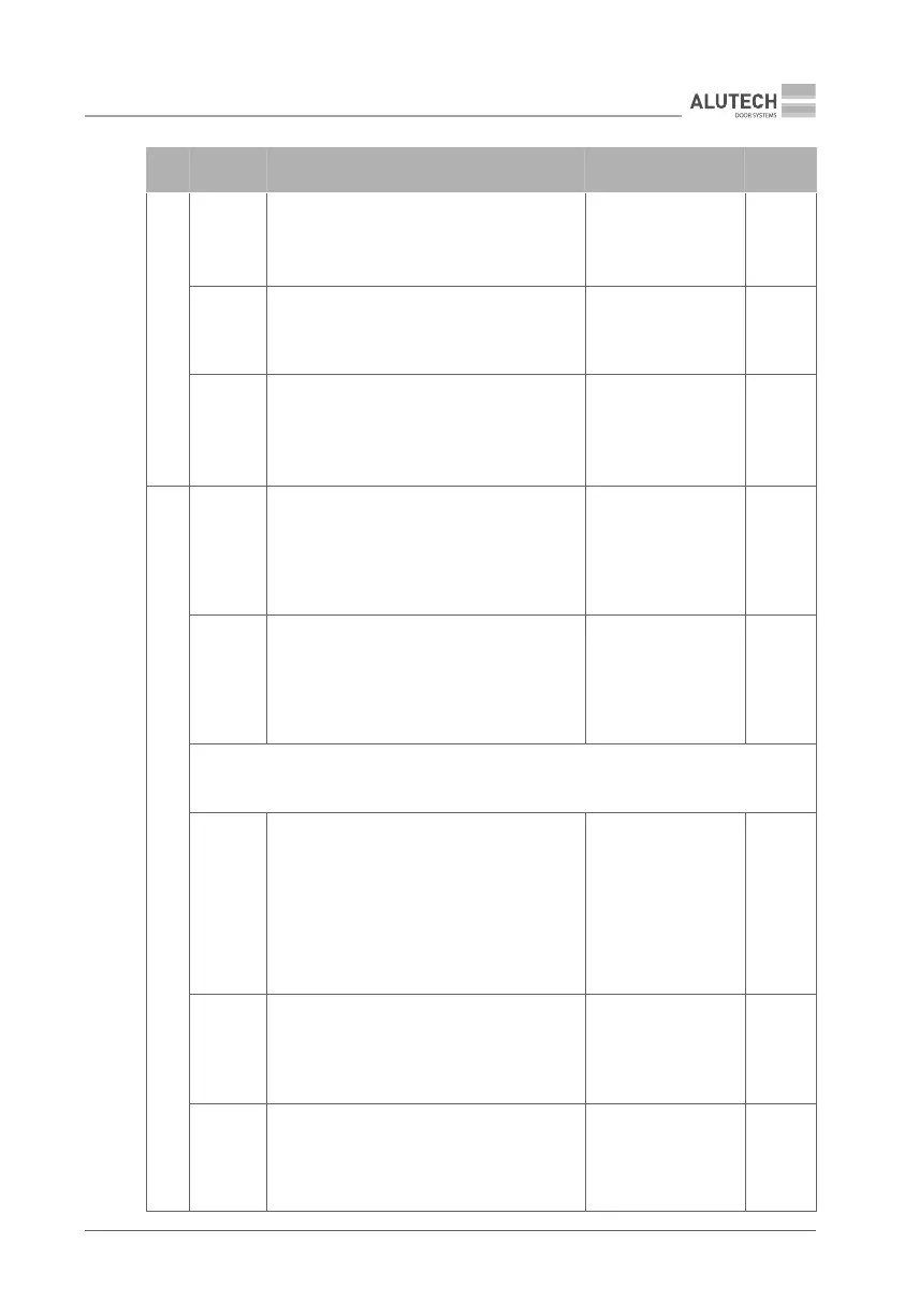
MENU SETTING DESCRIPTION VALUES
FACTORY
SETTING
P7
F4
Safety edge (SE input, Fig. 37, terminal
block2). Enables or disables Resistive edge
function (8.2kOhm)
no — disabled
on — enabled
no.
F5
ALR input operation (Fig. 37, terminal block 4).
Control input functions in either opening or
closing direction
OP — opening direction
CL — closing direction
O P.
F6
Electric lock activation time. Delay time to
start opening the electric lock provided that
outputs of terminal blocks 5–8 are properly
congured (values 15 or 16, Table 16)
0.2, 0.4…2.0:
0.2 — 0.2 s,
0.4 — 0.4 s,
2.0 — 2 s
0.4.
P8
F2
Movement start delay time (preliminary light
indication time). During the delay time, the
signal lamp will operate, the barrier lights will
be red (trac light, built-in barrier light, boom
illumination), indicating that movement will
start soon
no — disabled
01, 02…10:
01 — 1 s,
10 — 10 s
no.
F3
Lighting operating time after movement
stop. The setting is lighting lamp operating
time provided that 5–8 outputs are congured
properly (value 02, Table 16)
00, 01… 99:
00 — o after end of
movement (0 s),
01 — 10 s,
99 — 990 s (16.5 min)
03.
Y
When moving and during the delay time (P8–F2 setting), the lamp cannot be turned o
using the radio control command (see meaning of command on p. 16)
F4
Lighting operating time after LIGHTING ON
command is sent from the remote control.
Set operation time for the backlight lamp in
case you congure a remote control for light-
ing control purposes. (LIGHTING command,
Table 6)
no — lamp is not
switched o by
timeouts, only by
remote control
command
01, 02…99:
01 — 1 min,
99 — 99 min
05.
F5
Barrier red LED signal operation. Congure
the operation for the red color of the built-in
barrier LED lamp and boom backlight (Fig.
37, terminal block 9) when the barrier is fully
closed
no — disabled
on — enabled
no.
F6
Barrier LED signal operation. Select the op-
eration mode of the built-in LED barrier lamp
and boom backlight (Fig. 37, terminal block 9)
no — disabled
01 — enabled red light
02 — enabled red and
green light
02.