BOOM BARRIER BV58682626
SETUP
MENU SETTING DESCRIPTION VALUES
FACTORY
SETTING
P8
F7
LOAD 1 operating time after LOAD 1 ENA-
BLE remote control command. The setting
is terminal blocks 5–8 outputs operation
time (value 13, Table 16) in case a remote is
recorded to control a load (command LOAD1,
Table 6)
no — load not disabled
by timer (disabled
only by RC
command)
01, 02…99:
01 — 1 min,
99 — 99 min
no.
F8
LOAD 2 operating time after LOAD 2 ENA-
BLE remote control command. The setting
is terminal blocks 5–8 outputs operation
time (value 14, Table 16) in case a remote is
recorded to control a load (command LOAD
2, Table 6)
no.
P9
F1
MASTER / SLAVE Mode (simultaneous opera-
tion of two barriers, Fig. 42). Predene MASTER
and SLAVE barriers. Perform all add-on electric
connections and settings on the master
barrier. The slave barrier has active connection
inputs S, PH1, PH2, PHT, SE, CVR (Fig.37,
terminal block 4). Commands of remote
controls recorded in the slave barrier will not
be executed. If you want that only the master
gate be controlled, you can record a separate
button on the remote control (command value
17 or 18, Table 6)
no — disabled
01 — MASTER
02 — SLAVE
no.
Y
Before switching on the Synchronized operation mode, perform separate setup for each of
the barriers. (Section 5. Mains connection and open-close setting). Use equal (close) boom
lengths and set the same cycle times for both barriers.
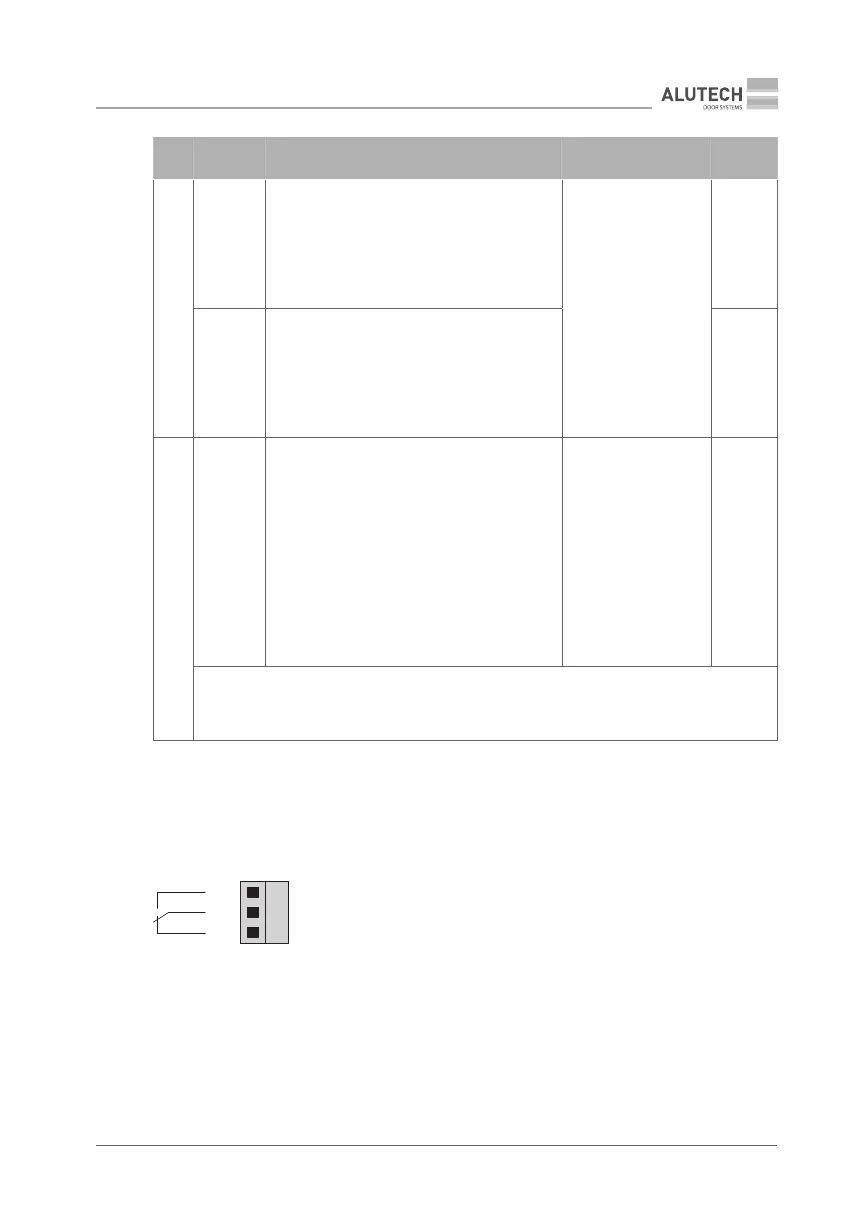
Table 16 shows operating modes of terminal blocks 5–8outputs (Fig. 37). When changing settings
(P3–F4…F7), the terminal outputs (relay contacts of the control unit) will operate in accordance
with preset logic. The following gure shows the normal state of the outputs (relay contacts of
the control unit).
NO
C
NC
NO — normally open contact
NC — normally closed contact