Device Connectors
17
Instruction Manual - Solecis Digital Switchers
Inputs and Outputs
The following sub-sections describe each component on the rear panel of the switchers. Refer to FIG. 3 on page 13 for
the complete layout of the rear panel.
HDMI INPUTS
The HDMI INPUT connectors on the rear panel route digital video (and audio) from connected source input devices to
the connected output devices. The SDX-410-DX features four connectors, while the SDX-810-DX features eight and the
SDX-510M-DX features three.These inputs support the following audio formats:
Dolby TrueHD
Dolby Digital
DTS-HD Master Audio™
DTS
Note: 2 CH through 8 CH L-PCM Dolby Digital and DTS support up to 48kHz, 5.1 channels.
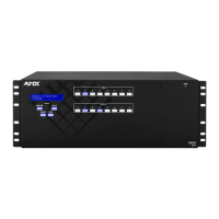
FIG. 10 displays the HDMI INPUTS for the SDX-410-DX.
FIG. 10 HDMI INPUTS
For more information about these connectors, including wiring, see the HDMI INPUTS section on page 21.
GROUP INPUTS (SDX-510M-DX only)
The two GROUP INPUTS areas on the rear panel each feature an HDMI port, a 15-pin VGA port, a 1/8" mini-Stereo
jack, and a 5-pin 3.5mm Dual External Button/LED Control connector.
The HDMI input supports a digital audio/video source. The VGA input port supports analog video. Use the 1/8"
mini-Stereo jack for analog audio. Though these two sets of input ports support separate digital and analog video
sources, you can only select one input at a time to be sourced to the output ports.
The SDX-510M-DX has two sets of groups in which the first external button LED control connector is used to cycle
through the inputs within a particular group. On the SDX-510M-DX, HDMI INPUT 1 is always the first input on both
groups. Group 1 contains inputs 1, 2, and 3. Group 2 contains inputs 1, 4, and 5. You can route the audio/video from one
input within a group at a time. You can cycle through the inputs in each group by clicking a single button module
connected to the External button connector located next to HDMI INPUT 1 on the rear panel of the device (see the
External Button/LED Control Connectors section on page 16 for more information about External button connectors.)
Note: With Group Input button switching, connection to a Master is not needed. The button press results in the switcher
directly cycling through the inputs in the group.
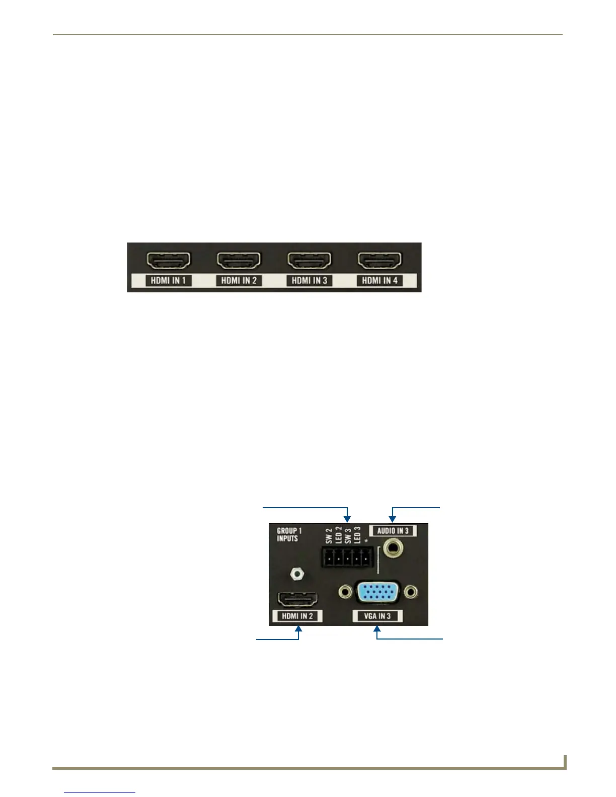
FIG. 11 displays the GROUP INPUTS area.
FIG. 11 GROUP INPUTS area
Note: Contact closures 3 and 5 are not tied to specific inputs, and are allowed for an auxiliary button press trigger event
notification which can be recognized by a NetLinx Master for programming purposes.
mini-Stereo jack
VGA portHDMI port
Dual External button/
LED Control connector

 Loading...