Wiring Specifications
22
Instruction Manual - Solecis Digital Switchers
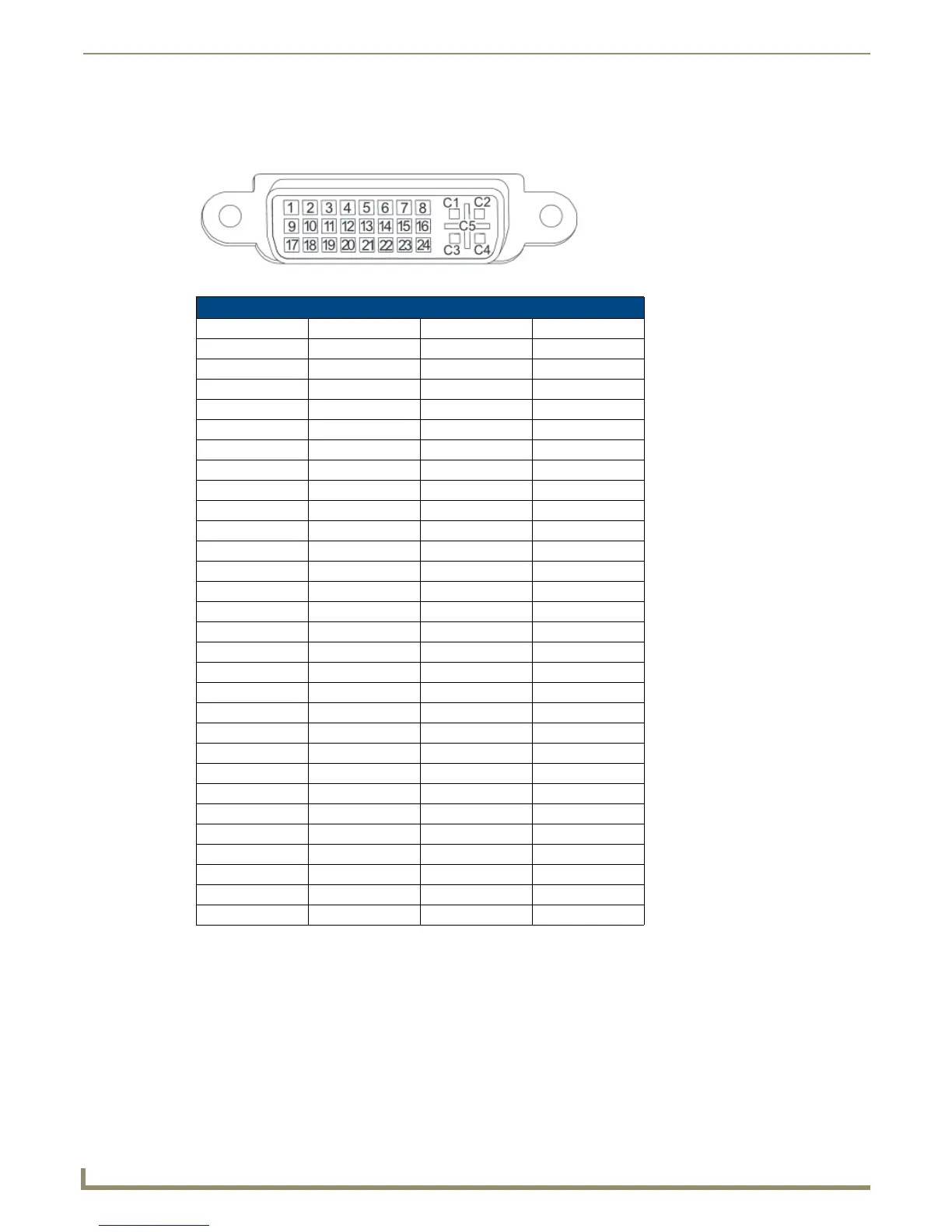
DVI Pinout for DVI-to-HDMI Cable Adapter
The pinout in FIG. 20 is for DVI-to-HDMI cable adapters which can be used with the modules when a DVI-I signal is
required.
FIG. 20 DVI pinout for DVI-to-HDMI cable adapter
*The +5 VDC on output pin 14 supplies a maximum of 55 mA.
Supported Audio Formats
The HDMI INPUT connectors on the rear panel route digital audio (and video) from connected source input devices to
the connected output devices. These inputs support the following audio formats:
Dolby TrueHD
Dolby Digital
DTS-HD Master Audio™
DTS
DVI Connector Pinout
DVI Input Pin # Signal Name DVI Output Pin # Signal Name
1 Data 2- 1 Data 2-
2 Data 2+ 2 Data 2+
3GND 3GND
4n/c 4n/c
5n/c 5n/c
6 DDC-CLK 6 DDC-CLK
7 DDC-Data 7 DDC-Data
8n/c 8n/c
9 Data 1- 9 Data 1-
10 Data 1+ 10 Data 1+
11 GND 11 GND
12 n/c 12 n/c
13 n/c 13 n/c
14 +5 VDC In 14 +5 VDC Out*
15 GND 15 GND
16 Hot-Detect 16 Hot-Detect
17 Data 0- 17 Data 0-
18 Data 0+ 18 Data 0+
19 GND 19 GND
20 n/c 20 n/c
21 n/c 21 n/c
22 GND 22 GND
23 CLK+ 23 CLK+
24 CLK- 24 CLK-
C1 n/c C1 n/c
C2 n/c C2 n/c
C3 n/c C3 n/c
C4 n/c C4 n/c
C5 n/c C5 n/c

 Loading...