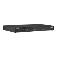
TPI-PRO-DVI (Total Presentation Interface-DVI)
14
TPI-PRO-DVI - Instruction Manual
TPI-PRO-DVI Specifications (Cont.)
•Supported Video
Resolutions:
Input DVI Video:
• up to 1920x1200
•single-link DVI only
Input Composite Video and S-Video:
•NTSC M/J
• NTSC 4.43
• PAL B/D/I/G/H
•PAL 60
•PAL M
•PAL N
•PAL Nc
•SECAM B/D/G/K/L
Input Component Video:
• NTSC 480i, 480p
• PAL 576i, 576p
• 720p, 1080i, 1080p
•Supported Audio
Sample Rates:
48000Hz, 44100Hz, 32000Hz, 24000Hz, 22050Hz, 16000Hz, 12000Hz, 11025Hz, and 8000Hz.
• Supported Input and
Output Modes:
See Appendix A: Supported Input and Output Modes on page 155.
Front Panel Components
• Power button/LED: Toggles the unit off and on.
Note: The TPI will power ON when the power supply is connected. Once power is applied, use the Power button
to toggle the unit off and on.
• Light Off: Power to the unit is either not plugged in, below approximately 10VDC, above approximately
19VDC, or cross-wired.
• Constant Green: Power to the unit is within nominal voltage limits (between 10VDC and 19VDC,
approximately), the unit is on, and all internal power supplies are operating normally.
• Constant Yellow: Power to the unit is within nominal voltage limits (between 10VDC and 19VDC,
approximately) and the unit has been turned off by pressing the power switch for more than two seconds.
• Flashing Yellow: Power to the unit is within nominal voltage limits (between 10VDC and 19VDC,
approximately), but one or more of the internal power supplies are not operating correctly. The unit needs
to be serviced. Contact AMX Technical Support for further instructions.
•USB Type-A
Host ports:
2 USB Type A ports for connecting up to one annotation touch monitor and up to one keyboard/mouse.
Note: Do not use a USB hub to connect multiple USB devices to the TPI.
• Serial port: DB9 connector (male) connects to a DB9 serial port on a PC, for serial communication.
• Status LED: • Constant ON: No communication with the NetLinx Master
• Blinking: In communication with the NetLinx Master
• Input LEDs: Yellow LEDs indicate a valid input signal on each source input (1-4 on the TPI-PRO-DVI-4, 1-2 on the
TPI-PRO-DVI-2).
• Buttons: Four white buttons provide access to the following configuration options:
• RESOLUTION: Opens a screen used to select the TPI output video signal resolution, ranging from
640 x 480@60Hz to 1920 x 1200@60Hz.
This output resolution setting must not be greater than the resolution on the connected panel.
Refer to the Setting the Output Resolution section on page 38.
• TOUCH: Opens the Panel Information page, where you can select from a series of serial touch panel drivers,
and select the driver that corresponds to the serial touch panel connected to the TPI (via the TOUCH INPUT
connector).
Refer to the Setting the Touch Drivers (Serial Touch Monitors Only) section on page 38 for more information.
• CALIBRATE: Opens the Calibration page, displaying a series of crosshairs. These crosshairs are used to
calibrate the touch device being used.
Refer to the Calibrating the TPI section on page 39.
• SETUP: Opens the TPI firmware setup menu.
Refer to the TPI Configuration Pages section on page 52.
Rear Panel Components
• DVI-I Inputs: DVI-I input connectors, one per input source (1-4 on the TPI-PRO-DVI-4, 1-2 on the TPI-PRO-2).
Each input connector supports VGA graphics, S-video, composite video, component video, and DVI input.

 Loading...