Appendix B: Using NetLinx Studio to Connect to a NetLinx Master
160
TPI-PRO-DVI - Instruction Manual
6. In the Online Tree, right-click and select Refresh System from the context menu to attempt to establish the specified
connection.
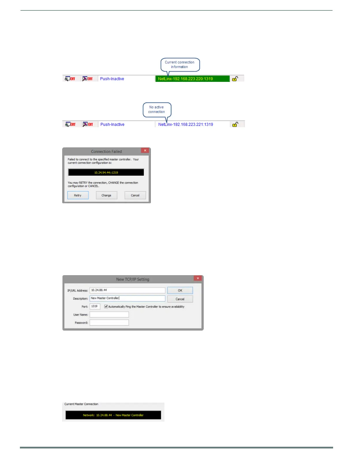
If the connection is successful, the connection information is indicated in the Status Bar and highlighted in green/yellow
(FIG. 128).
If the connection fails, the Status Bar indicates no active connection (FIG. 129).
The program will prompt you to revisit the current communication settings (FIG. 130).
If you receive this message, try the following:
Click Retry to attempt the connection again, using the same settings.
Click Change to re-visit the Workspace Communication Settings dialog to edit the current settings.
Click Cancel to close the dialog without establishing a connection.
Manually Entering the Master’s IP Address Information
NOTE: Click Settings > Workspace Communications Settings to open the Workspace Communication Settings dialog, and click the
System Settings or Default Settings button to open the Communications Settings dialog.
1. In the Communications Settings dialog (Network tab), click New to open the New TCP/IP Setting dialog (FIG. 131).
2. Enter the TCP/IP Address for the target Master Controller.
3. Enter a Description.
NOTE: The Port should always be set to 1319 (default setting). Do not change the Port assignment.
4. Leave the Automatically Ping the Master to ensure availability option selected.
5. Enter the User Name and Password required by the target Master (only if the Master is secured).
6. Click OK to close this dialog and return to the Communications Settings dialog. The new Master’s IP Address is indicated in the
List of Addresses.
7. Select the new Master connection in the List of Addresses. This populates the Current Master Connection field (FIG. 132).
FIG. 128
Status Bar indicating a Network connection to a Master Controller
FIG. 129 Status Bar indicating NO Network connection to a Master Controller
FIG. 130 Connection Failed
FIG. 131 New TCP/IP Setting dialog (indicating sample IP information)
FIG. 132 Communications Settings dialog indicating the selected Master connection
 Loading...