UDM-0808-SIG Wiring and Connections
10
UDM-0808-SIG, UDM-RX02N and UDM-ABB-8-SIG Operation /Reference Guide
Serial Port - Default Communication Settings
Use hyper terminal with default serial settings to communicate with the UDM-0808-SIG (and UDM-RX02N):
DB9-to-RJ12 Adapter Cable Pinouts
The following table provides the pinout configuration for the DB9-to-RJ12 (FG-RS01, not included) adapter
cable:
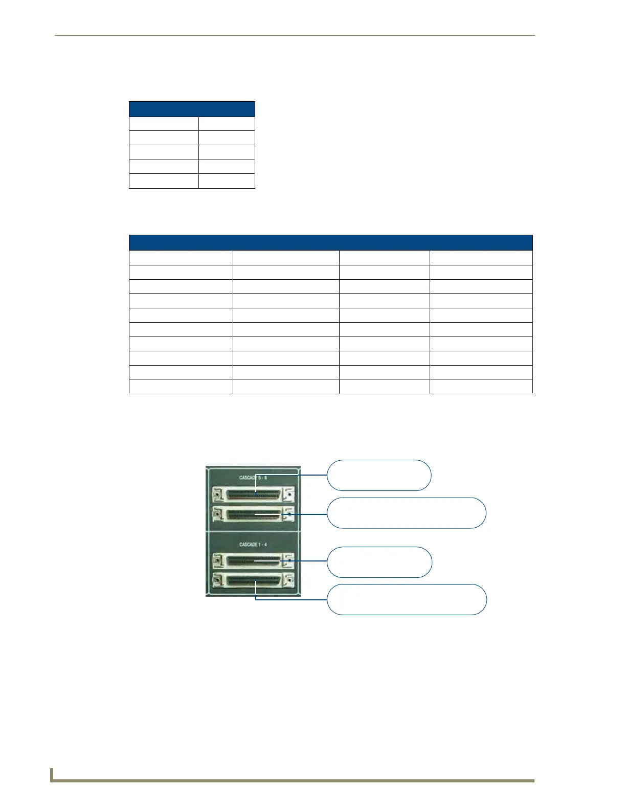
CASCADE Ports
The CASCADE ports allow UDM-0808-SIG Hubs to be chained together to increase the number of outputs
which can be delivered to the end points. The CASCADE IN and OUT connectors on the UDM Hubs require a
UDM-EXP-02 Cascade Cable (FG-1402-71 - not included).
The CASCADE (Out) ports can also be used to send audio to the UDM-ABB-8-SIG Signature Series Audio
Breakout Box (FG1402-60). Refer to the UDM-ABB-8-SIG Audio Breakout Box section on page 71 for
details.
Refer to the Cascading Hubs section on page 77 for details on configuring cascaded Hubs.
Default Serial Settings
Baud Rate: 115200
Data Bits: 8
Parity: None
Stop Bits: 1
Flow Control: None
DB9-to-RJ12 Adapter Cable Pinouts
DB9 connector Function Abbreviation RJ12 connector
Pin 1 Not used NC
Pin 2 Transmit Data TD or TX or TXD Pin 2
Pin 3 Receive Data RD or RX or RXD Pin 3
Pin 4 Data Set Ready DSR Pin 1
Pin 5 Signal Ground GND Pin 4, 5
Pin 6 Data Terminal Ready DTR Pin 6
Pin 7 Not Used NC
Pin 8 Not Used NC
Pin 9 Not Used NC
FIG. 10
Cascade 5-8, 1-4 Ports
CASCADE 5-8 IN
CASCADE 5-8 OUT
CASCADE 1-4 IN
CASCADE 1-4 OUT
To another UDM Hub or
UDM-ABB-8-SIG (CASCADE IN port)
From source UDM Hub
(CASCADE OUT port)
From source UDM Hub
(CASCADE OUT port)
To another UDM Hub or
UDM-ABB-8-SIG (CASCADE IN port)
 Loading...